Testing · 02
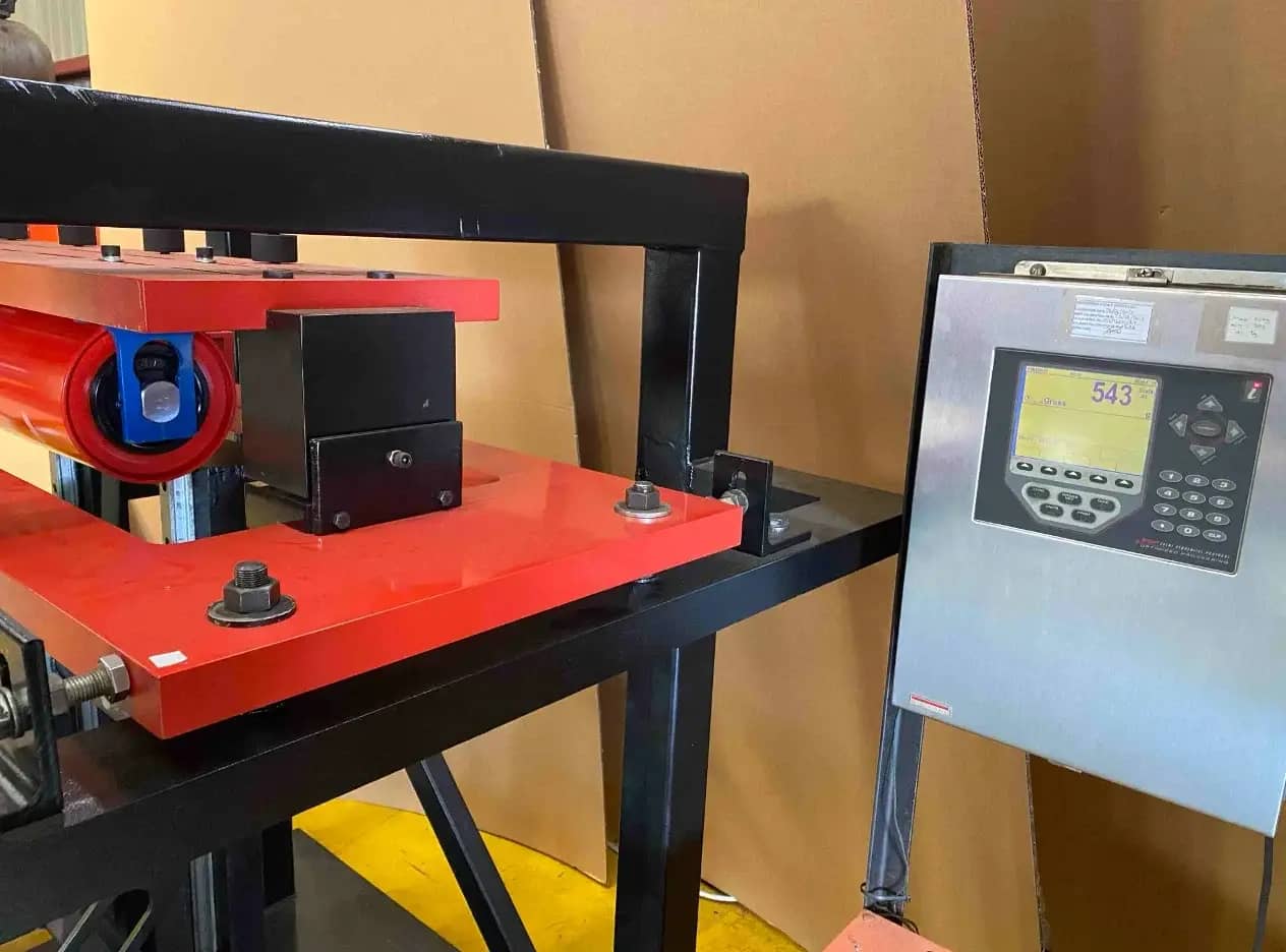
Friction test
Confirms the idler turns freely under load by measuring running resistance and bearing efficiency.
Idler frames and rollers that support, align and cushion the belt, from light handling to the heaviest mining service.
An idler holds the belt true and keeps turning through dust, impact and weather. The geometry is simple. Service life in the field is where the engineering goes.
Our core design has proven itself in the field for decades. Over that time, we have continuously refined what dictates service life: tighter manufacturing tolerances, better seal arrangements and improved coatings, each change tested before it reaches a conveyor.
The result is a design operations already rely on, and every frame meets the same standard before it leaves the floor.
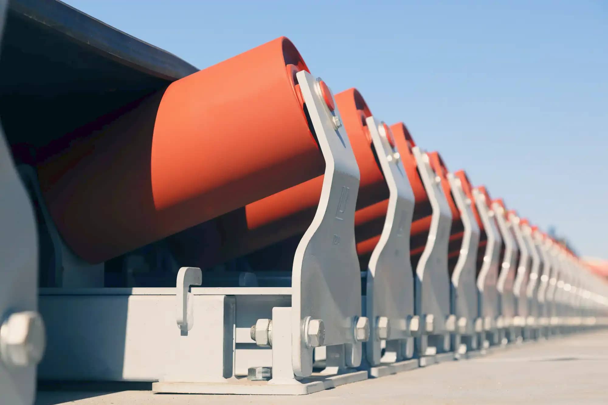
Precise, repeatable frame dimensions from one idler to the next keep the belt line true, limiting the loads that belt deviation causes and helping the belt track.
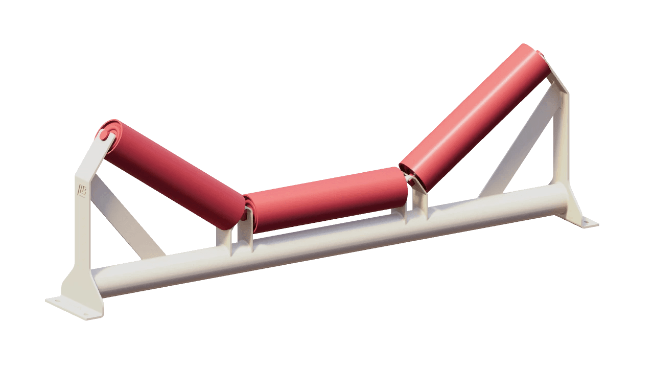
Supports and profiles the loaded belt on three equal rollers in line, the most widely used carrying idler. It carries high loads in a compact frame that is practical to transport and handle.
Learn more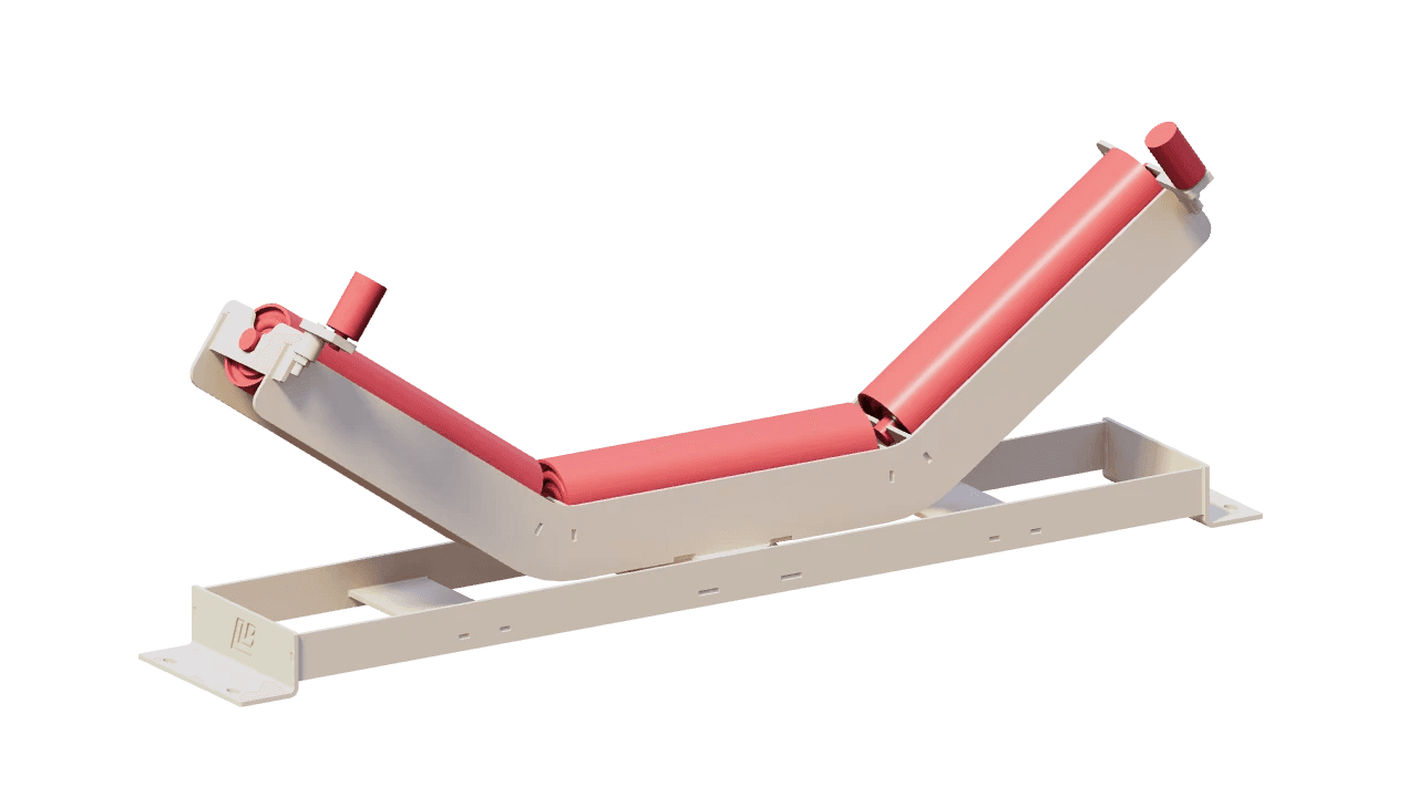
Steers a wandering belt back to centre on its own. When the belt bears against a guide roller at either end, the pivoting frame swivels and the angled rollers correct its path, with no manual adjustment.
Learn more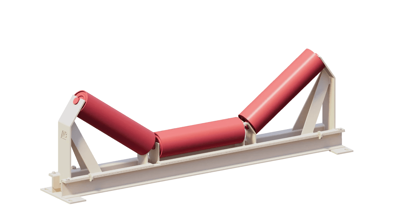
Carries the belt on a standard three-roller trough whose frame retracts, drawing the rollers out to the side for inspection and change-out without lifting the belt or working above or below it. It keeps rollers serviceable where stoppages must be short or the structure is hard to reach.
Learn more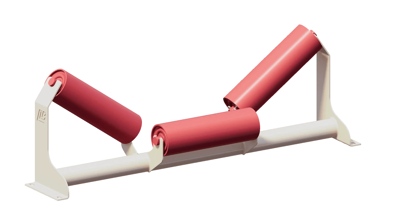
Supports the belt continuously across its full width, with three rollers staggered along the direction of travel so their ends overlap at the wing-to-centre junctions. The overlap closes the gap between roller ends and lets the idler sit lower than an equivalent inline frame.
Learn more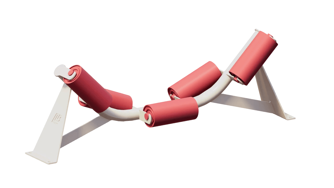
Forms a deep, smoothly curved trough for wide, high-capacity belts, with the load shared across five staggered rollers and a smaller change of angle at each roller junction.
Learn more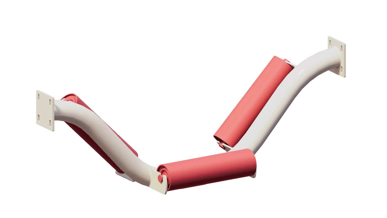
Supports the belt on continuous, overlapping rollers in a low-profile frame: three offset rollers on a single bent tube, staggered fore and aft.
Learn more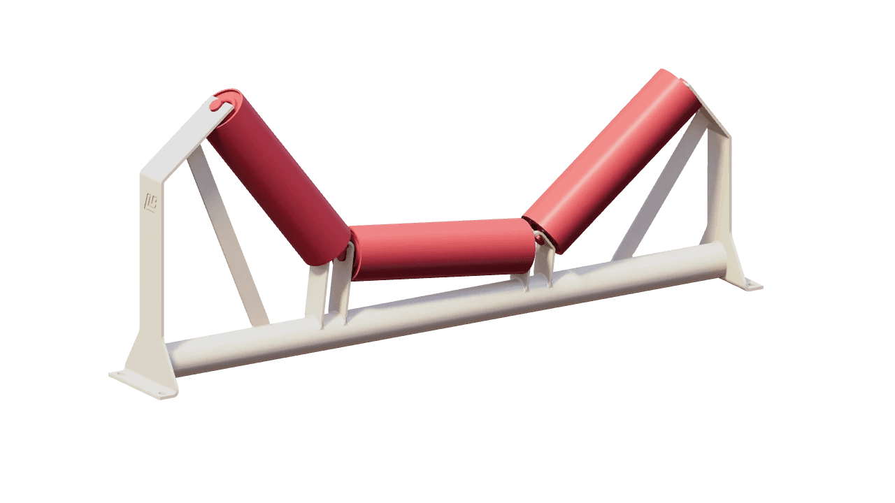
Keeps the loaded belt centred through horizontal curves. The idler is banked with its inner side raised, so the weight of the belt and load pushes outward against the inward pull of belt tension.
Learn more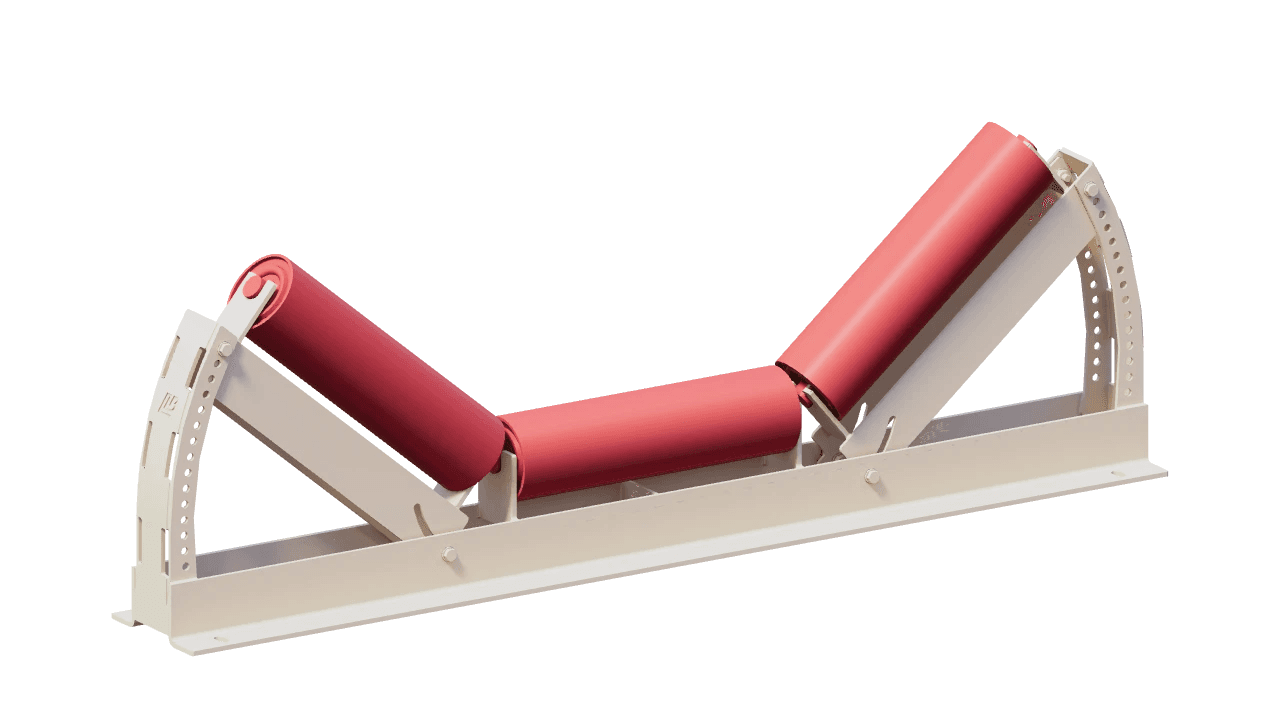
Eases the belt between flat at the pulley and fully troughed, with a wing-roller angle set by bolt position for the transition zone.
Learn more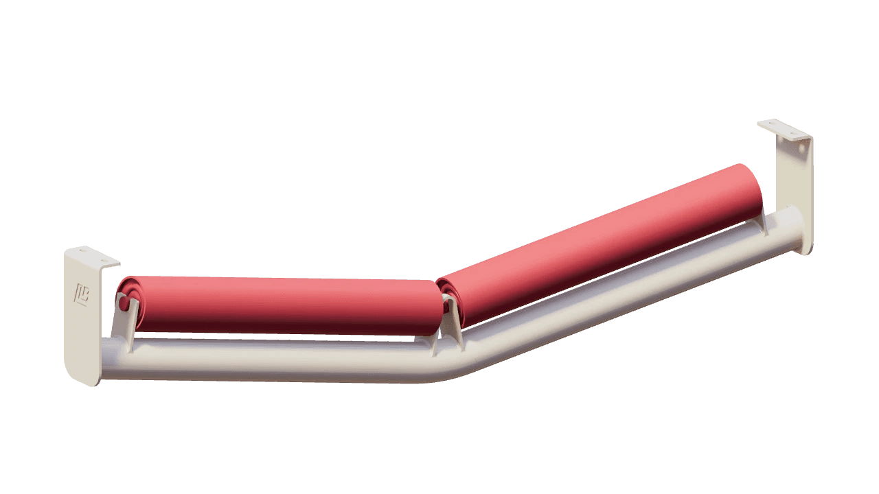
Keeps the empty return belt centred on two rollers set in a shallow V, which give it a gentle trough.
Learn more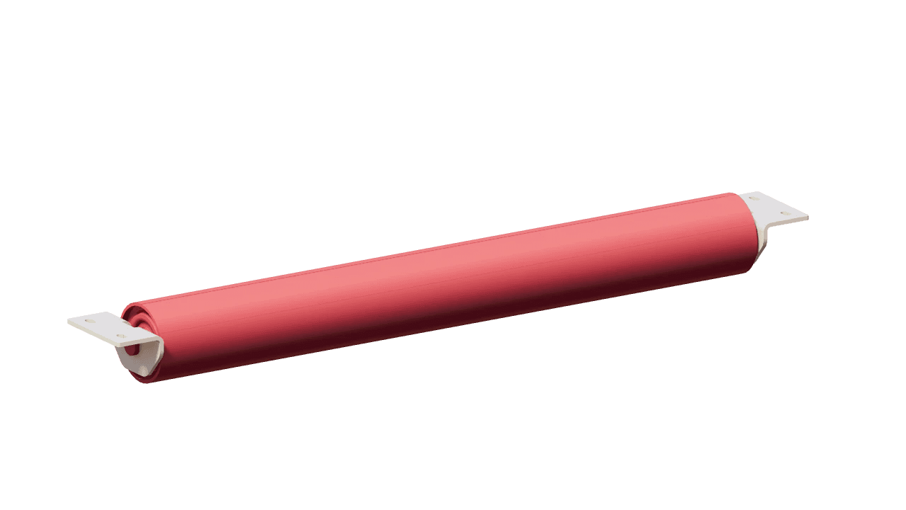
Supports the empty belt on its run back to the tail on a single flat roller, the simplest return idler.
Learn more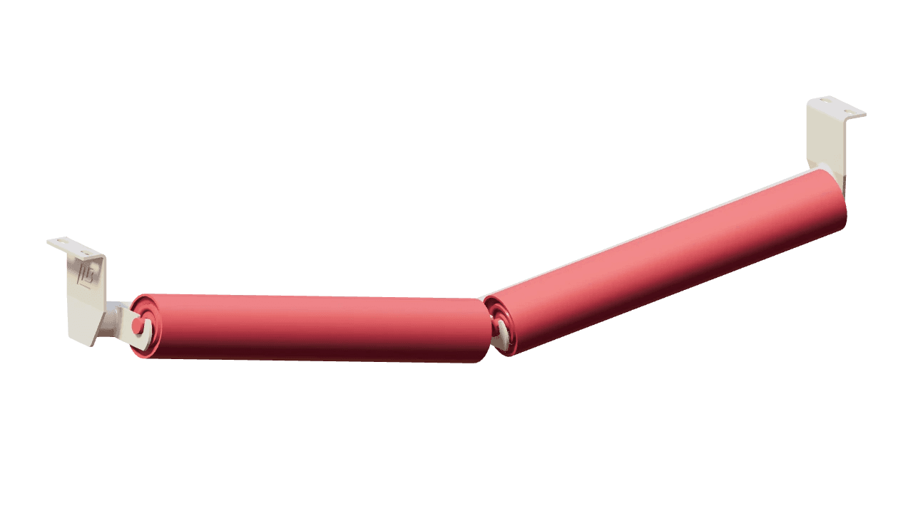
Lowers the overall height of a symmetric two-roller V-return by offsetting both rollers clear of the frame's cross-member.
Learn more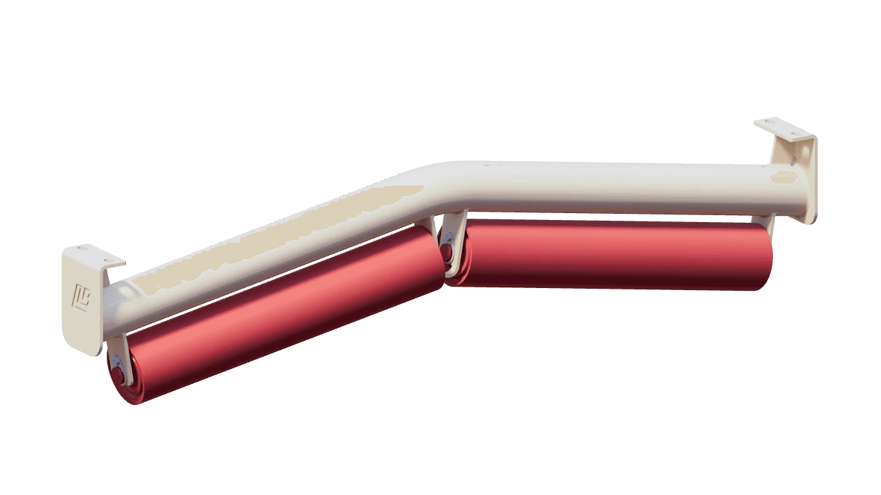
Steers the return belt back to centre from above. Belt tension holds the clean side of the belt up against two rollers set in an inverted V, which form a channel that tracks the belt positively.
Learn more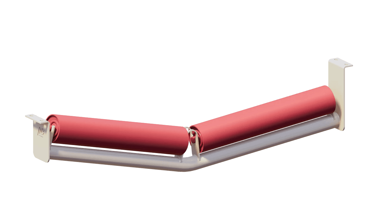
Keeps the return belt centred through horizontal curves. The V-return idler is banked with its inner side raised, so the weight of the belt pushes outward against the inward pull of belt tension.
Learn more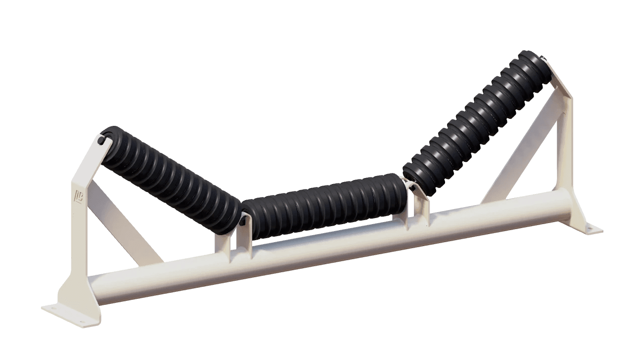
Absorbs the energy of material falling onto the belt, with cushioned impact rollers in a troughed carrying idler.
Learn more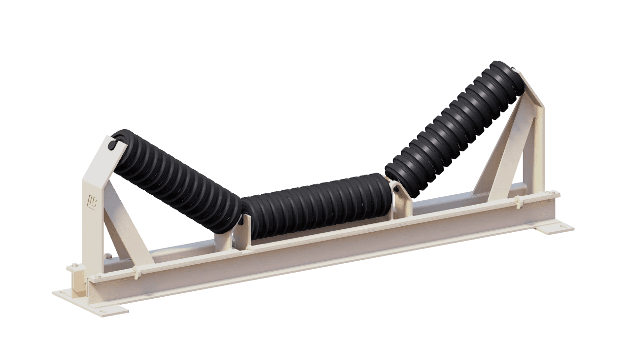
Absorbs material impact in the loading zone on a cushioned trough whose rollers pull out on a retractable frame for replacement, with the belt left in place.
Learn more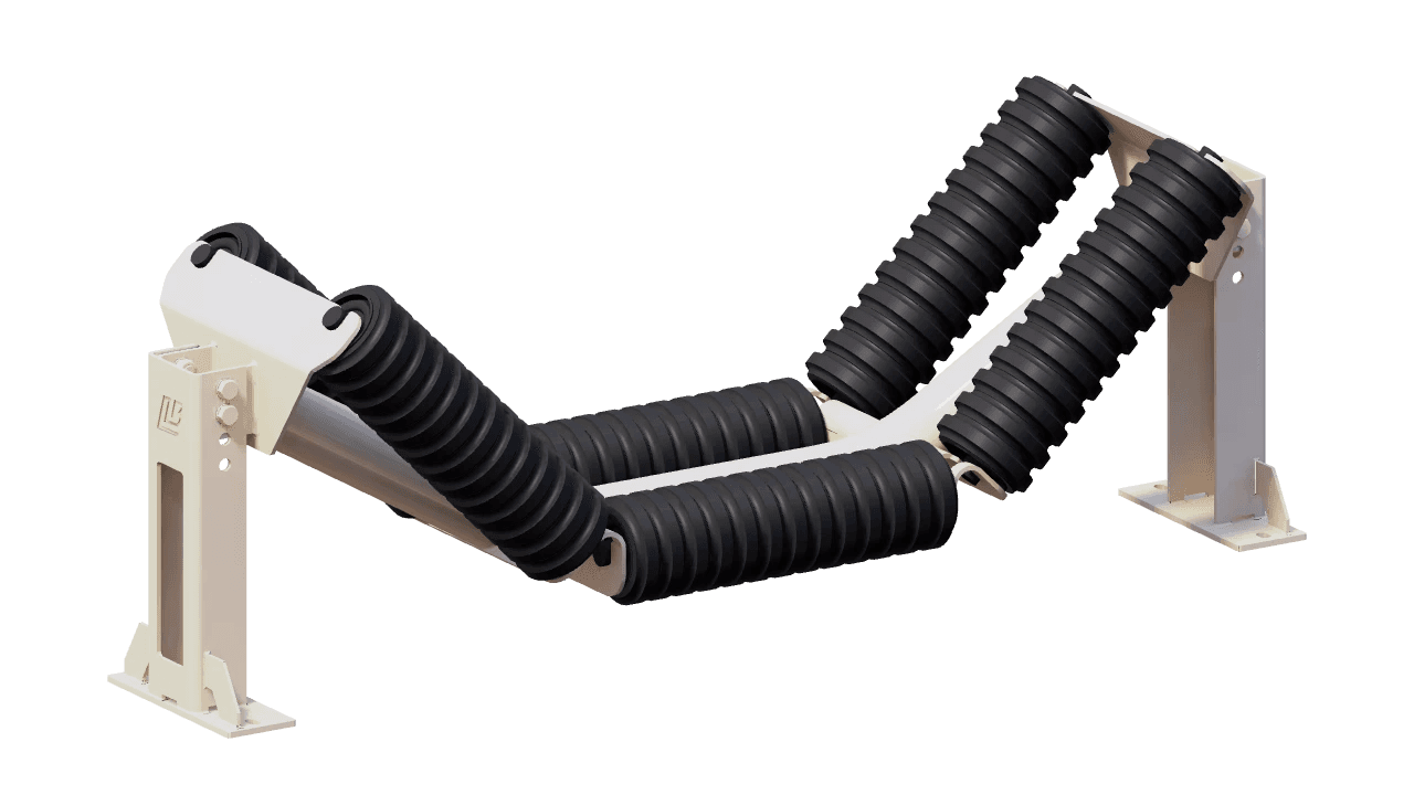
Absorbs impact across an extended bed of six rubber-cushioned rollers, two three-roller troughs in line, on a frame that lowers as one unit so the rollers change out without dismantling the structure around them.
Learn more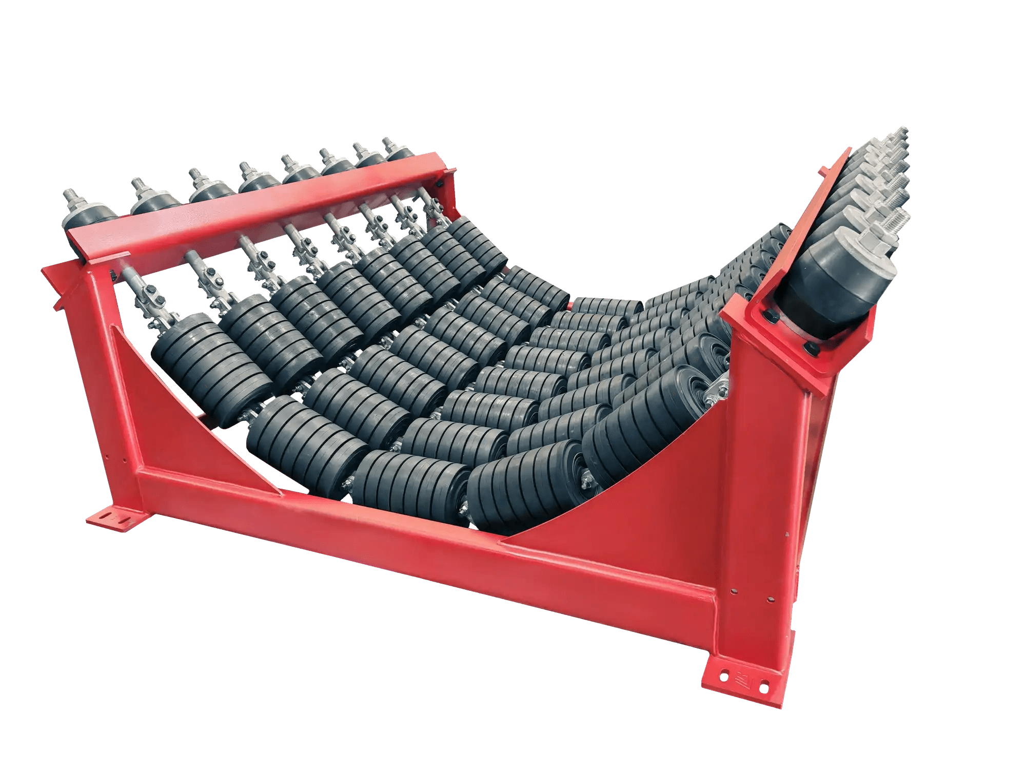
Cushions lump impact under loading and transfer chutes and keeps the belt sealed against the skirting, in garland, impact bar and roller, and slider bed designs.
Learn moreDimensional inspection, weld integrity, coating adhesion and roller running checks, following the inspection and test plan for each order.
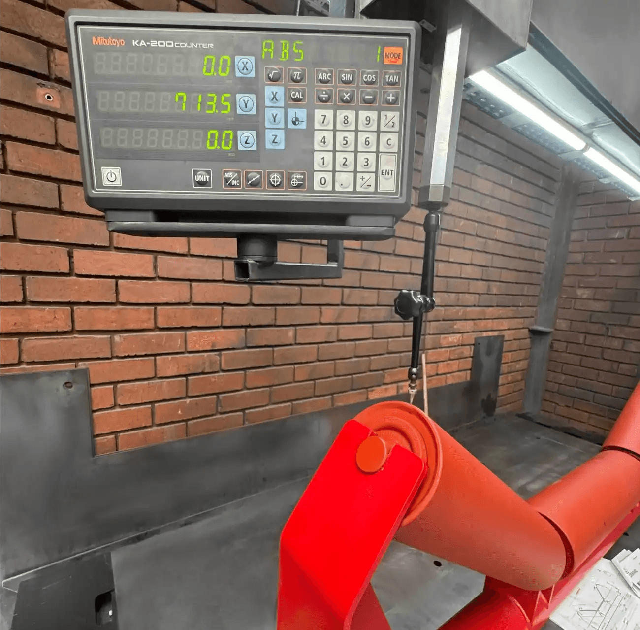
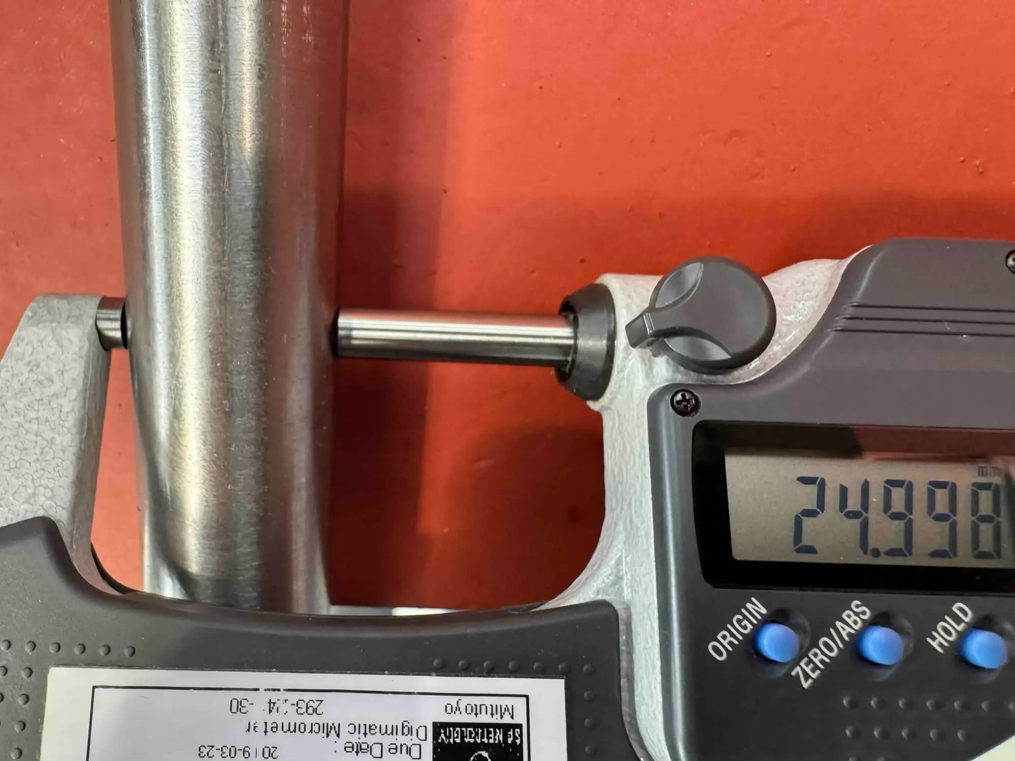
We check frame and roller dimensions to confirm fit, mounting centres, roller spacing and installation accuracy before dispatch.
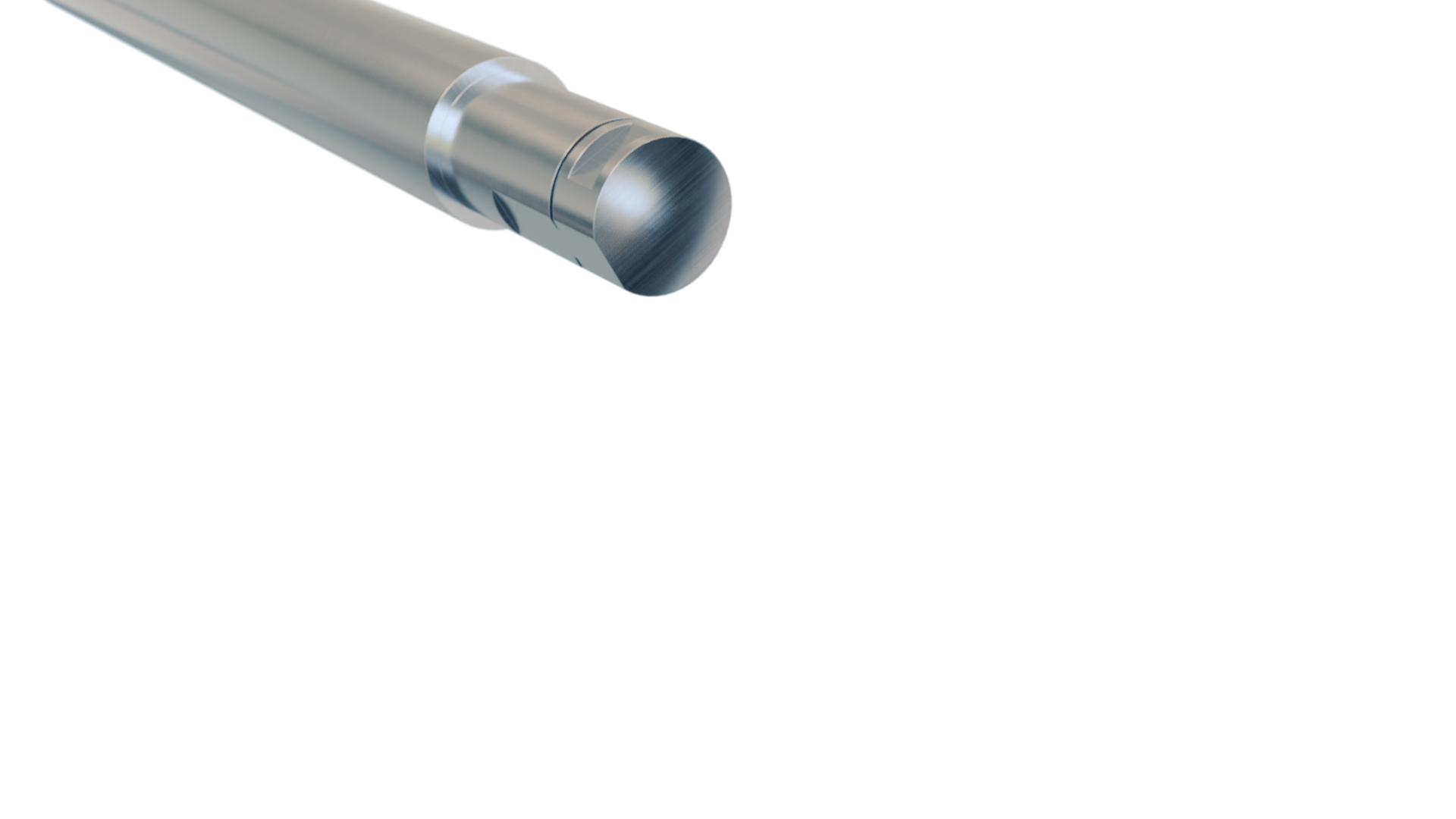
Confirms the idler turns freely under load by measuring running resistance and bearing efficiency.
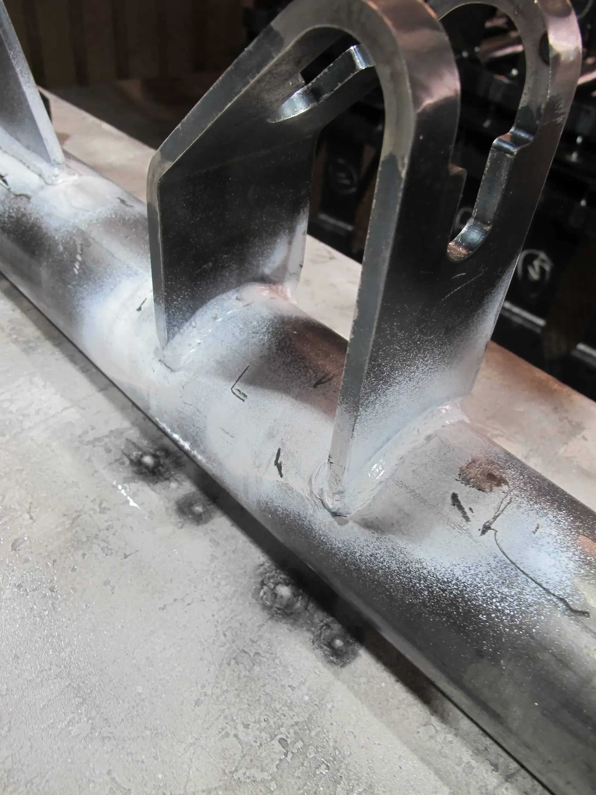
Non-destructive inspection of frame welds to find hairline cracks before dispatch.
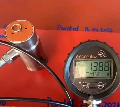
Verifies the bond between coating and steel so the finish protects the frame through its service life.
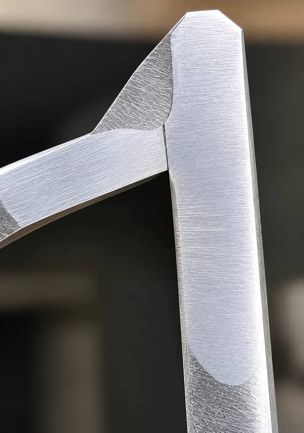
Polished, etched cross-sections of sample roller welds confirm full penetration and sound structure.
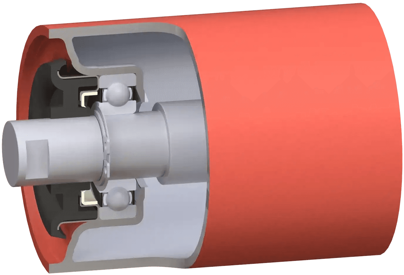
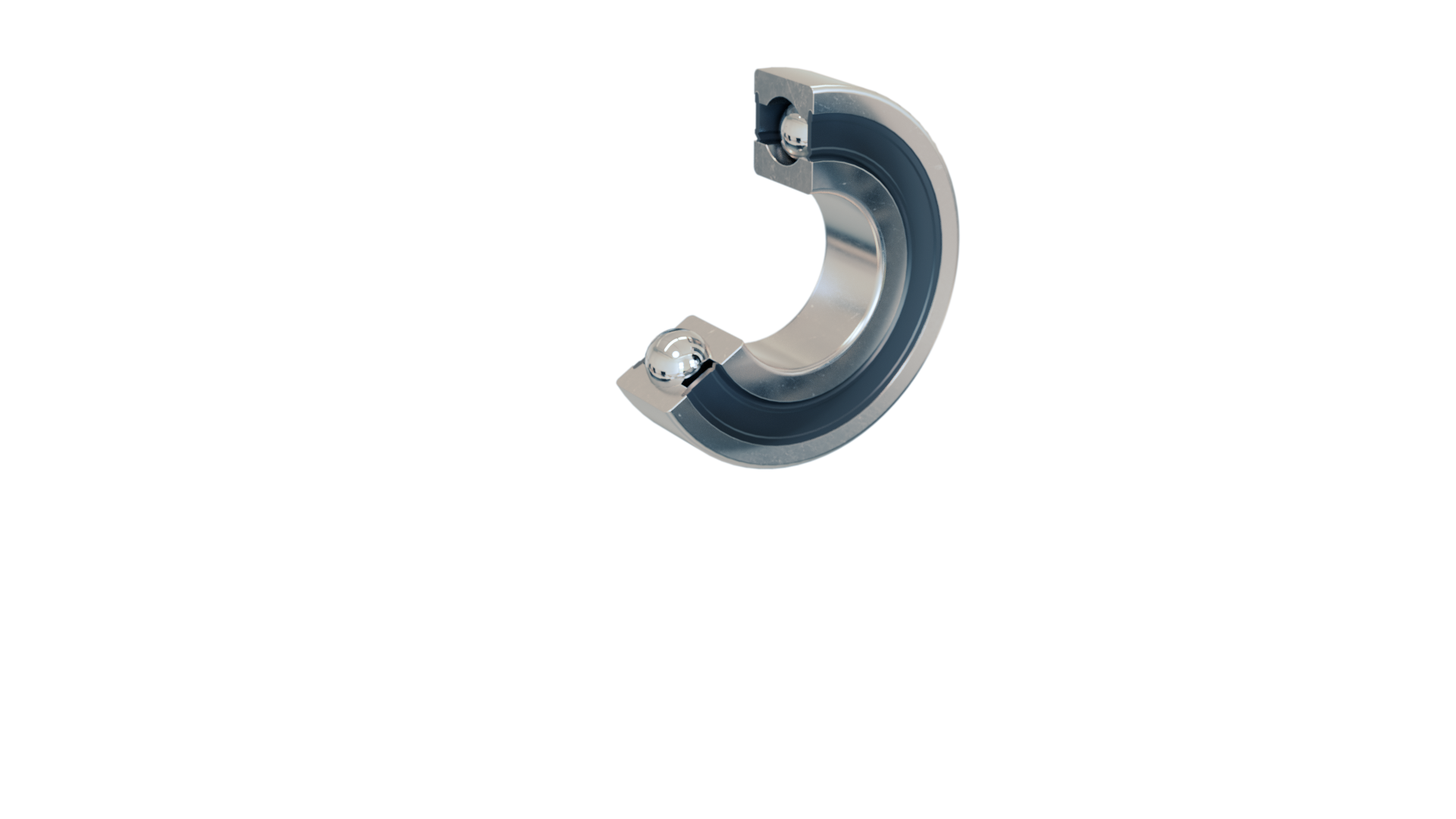
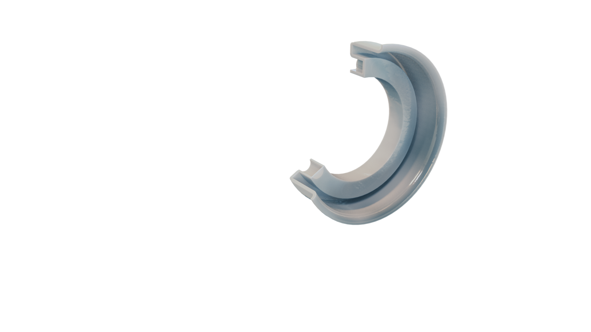
Accurate bearing seats and multi-stage seals give long bearing life and low running resistance, across steel, composite, lined, hybrid, stainless and impact constructions. The full range, internal construction and test data are on the Rollers page.
A self-powered sensor built into the roller seal, driven by the roller's own rotation, reads bearing temperature, vibration and speed and transmits without wiring. It flags a failing roller early enough to replace it before it damages the belt.
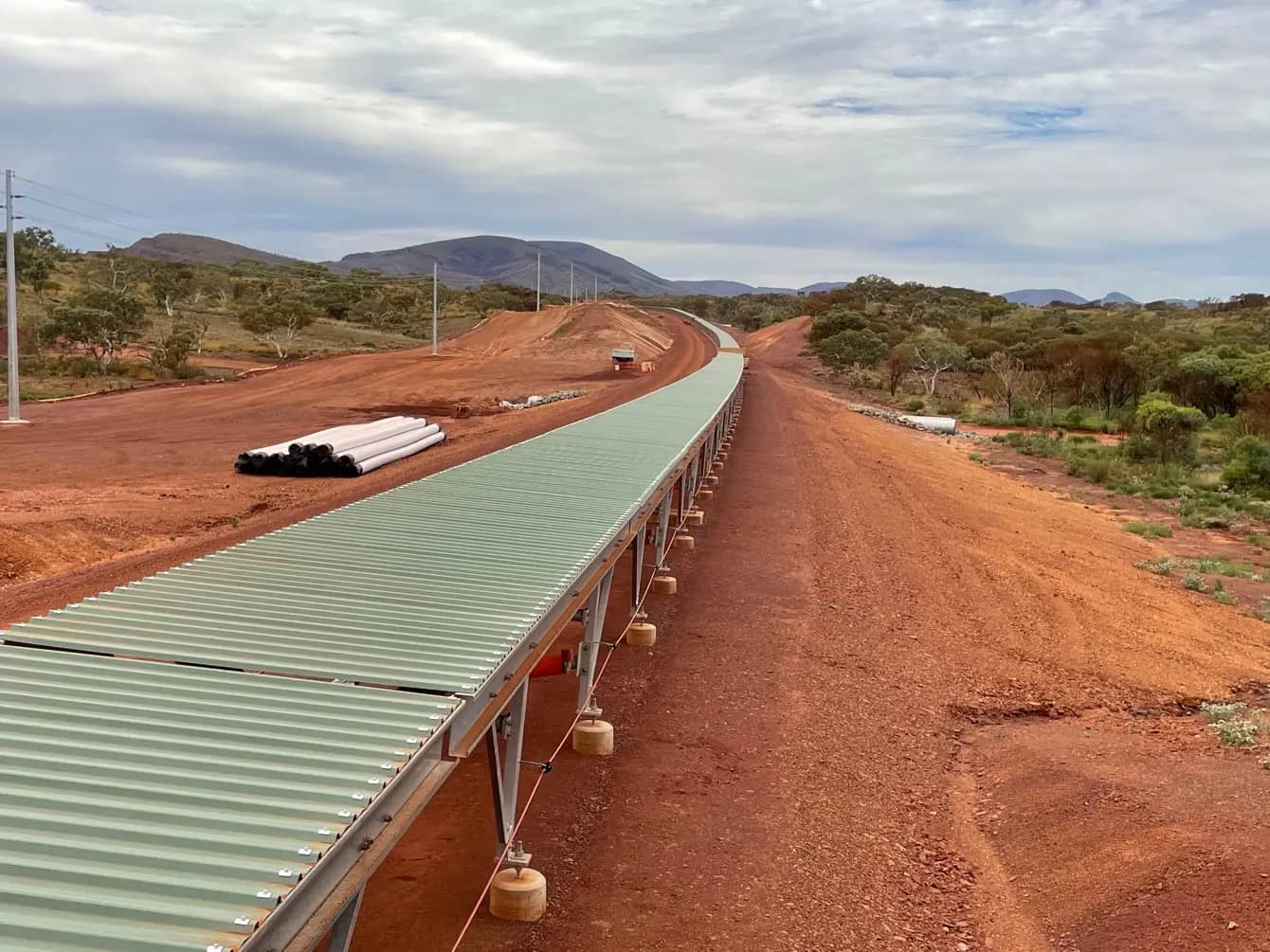
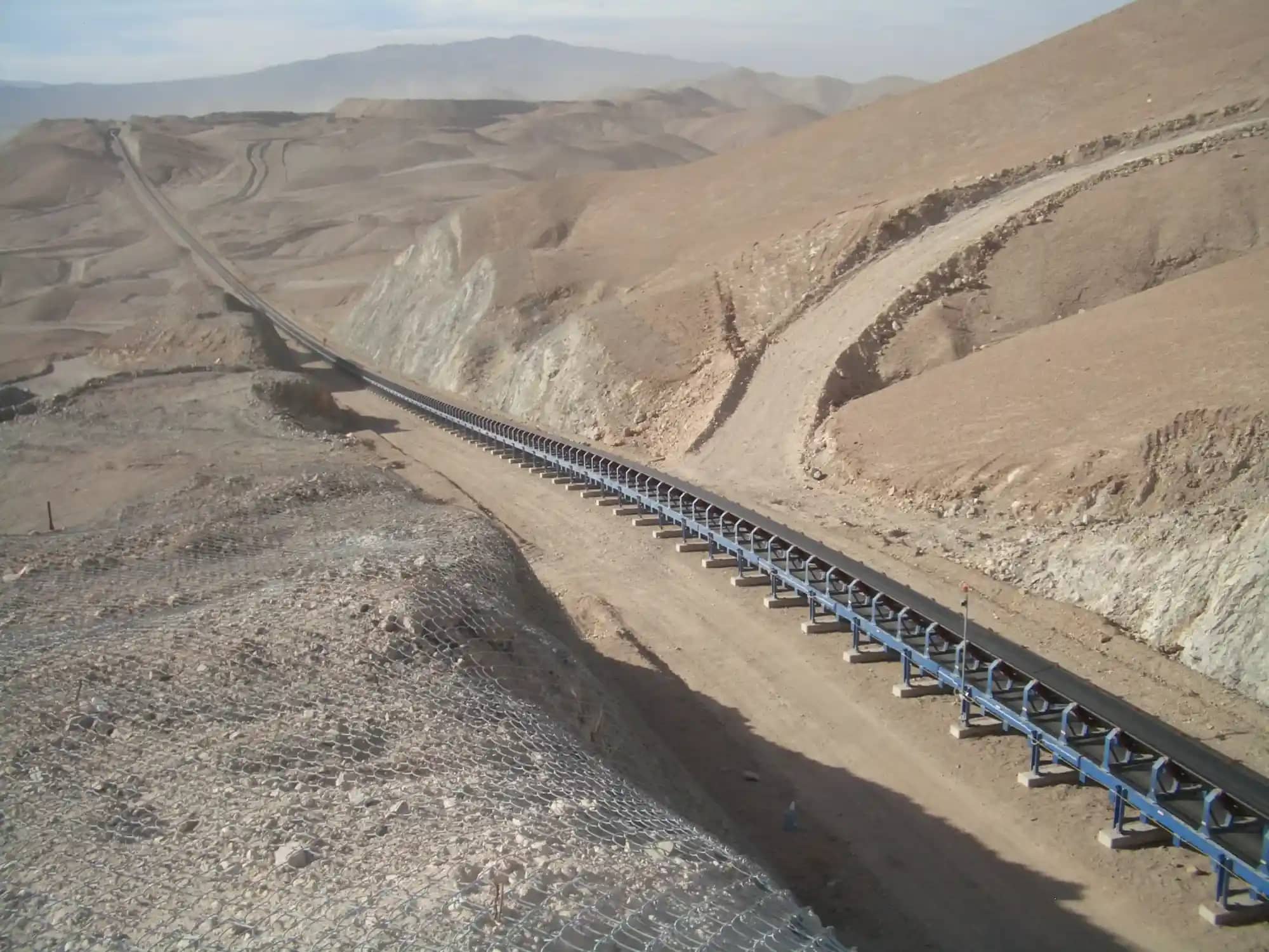
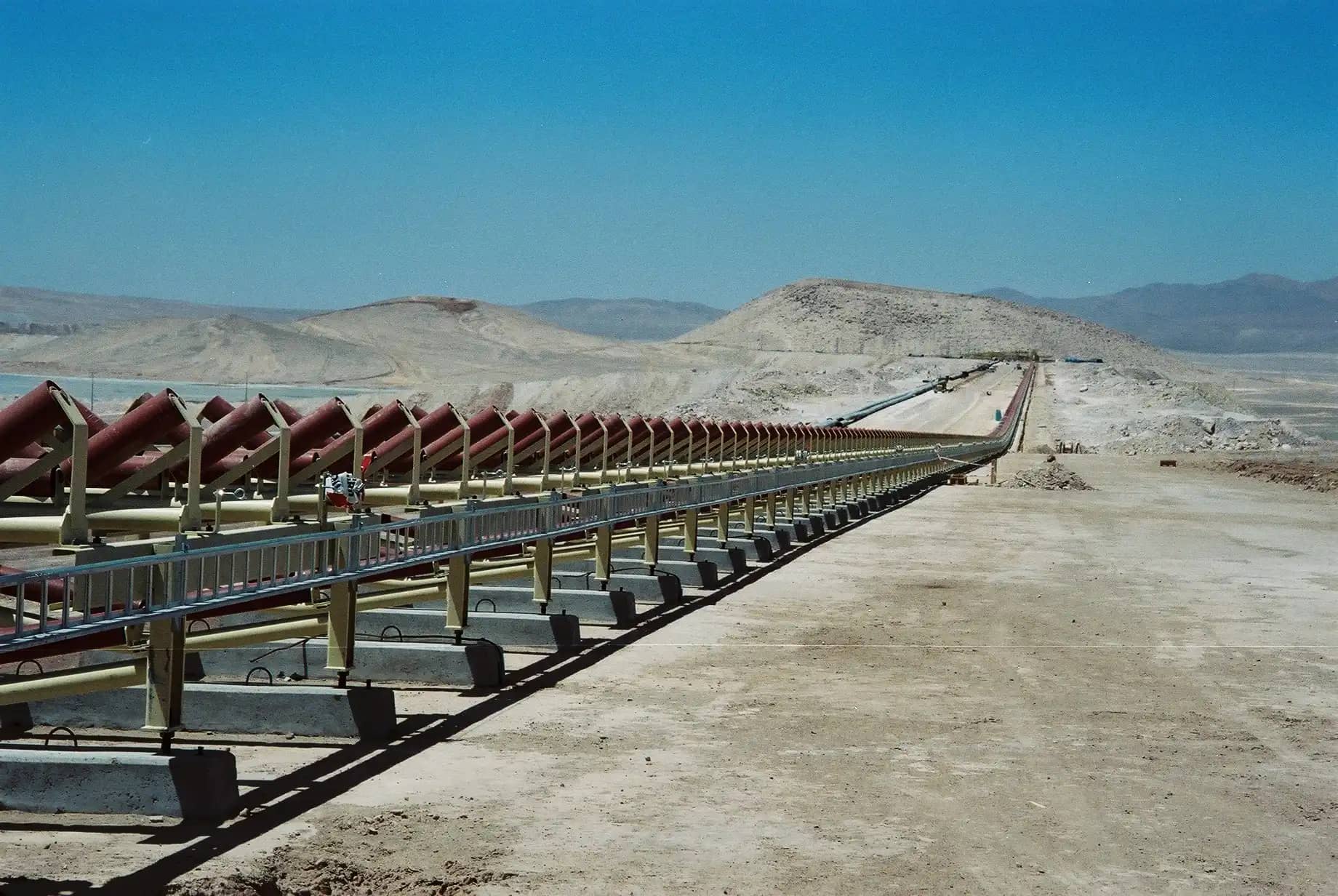
Lorbrand carry idler frames and rollers on the 13 km overland conveyor that moves in-pit-crushed ore to the Greater Tom Price hub.
2020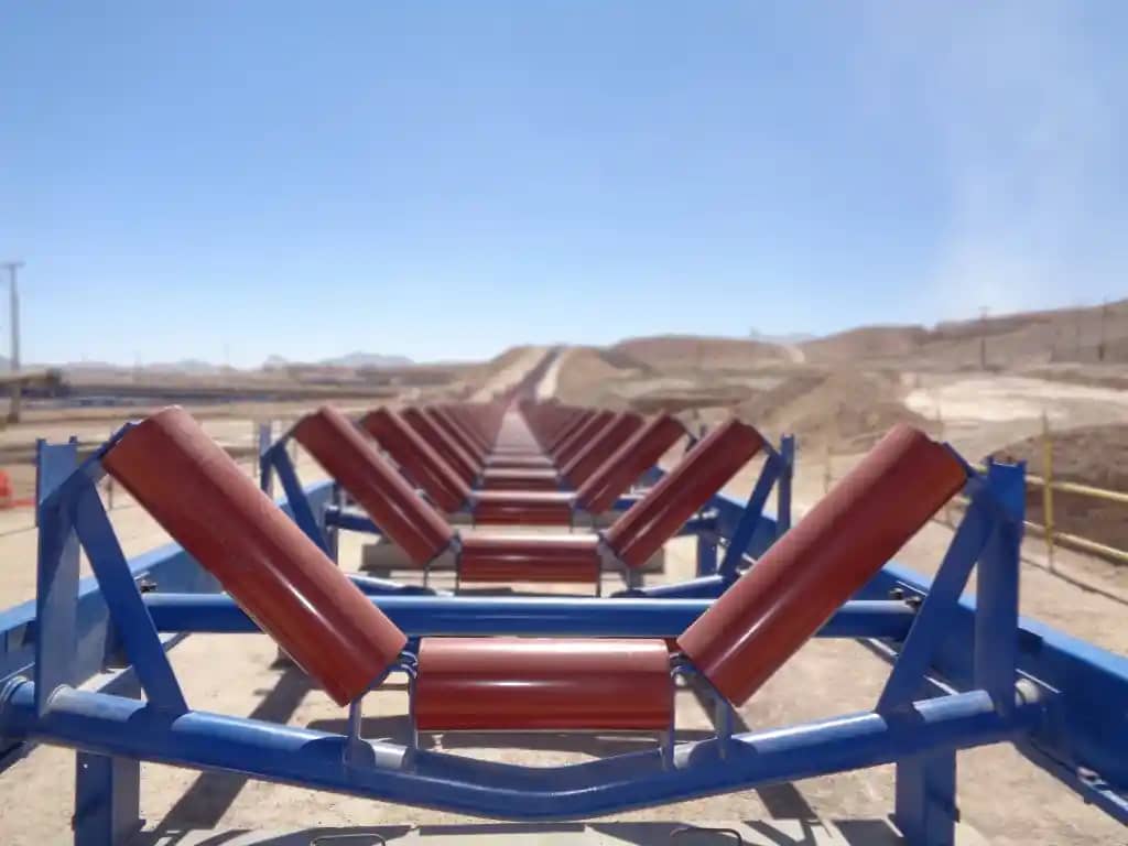
Lorbrand idlers run in what is widely called the most powerful conveyor belt installation on Earth, carrying ore from the block cave beneath the world's largest open-pit copper mine.
2016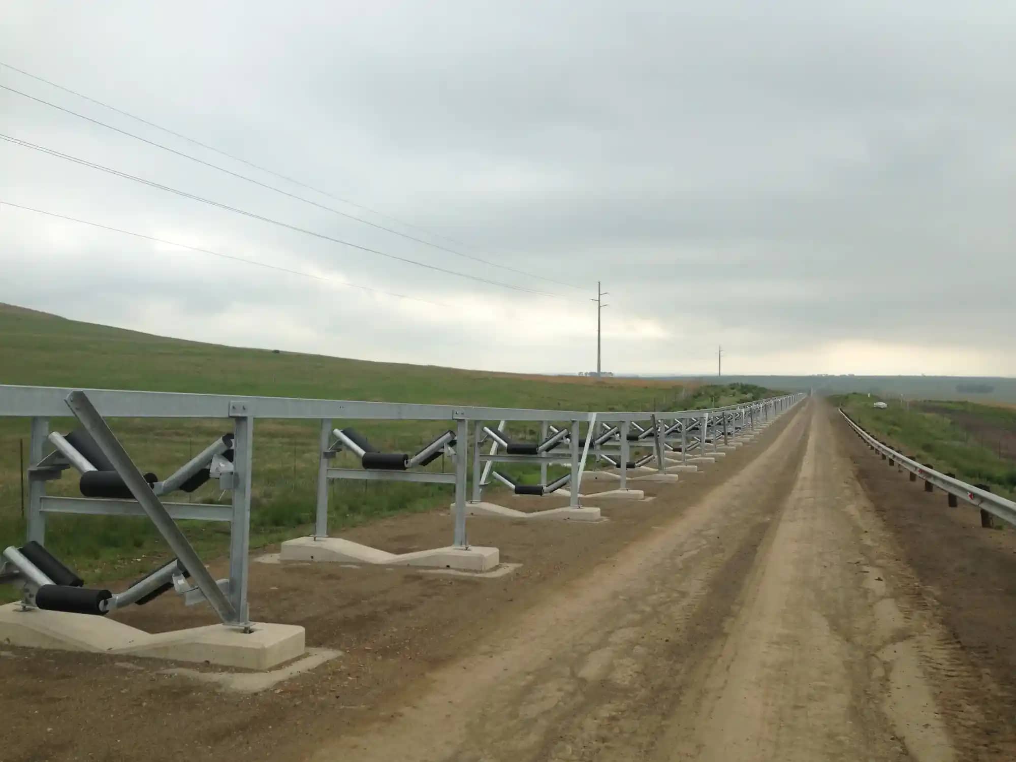
The world's longest single-flight conventional belt conveyor, with Lorbrand the sole idler and pulley supplier.
2015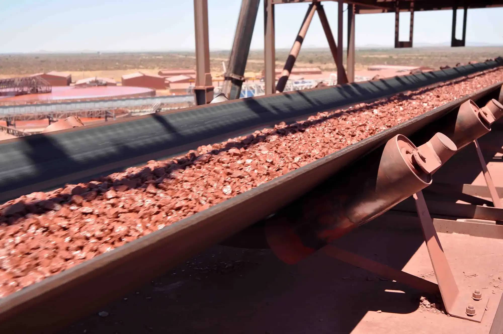
Lorbrand idlers, more than 90,000 rollers, for a greenfield 10 Mt/y iron ore mine in the Northern Cape, originally the Bruce, King and Mokaning (BKM) project.
20084 of 10 references. All projects