Contact Traces and Failure Analysis of Deep Groove Ball Bearings in Conveyor Idler Rollers
Reading the running tracks of idler roller bearings, recognising the common failure modes, and dismantling a bearing so the evidence survives
Lorbrand Engineering16 September 20267 min read
Introduction
Investigating bearings, both before and after ultimate failure, is a highly useful practice. The primary goal is to understand the cause of failure so that future incidents can be minimised or appropriate remedial action can be taken.
This guide covers the wear patterns and failure modes of deep groove ball bearings used in conveyor idler rollers, where the inner rings are stationary and the outer rings rotate. An analysis of the rollers themselves is equally essential but is outside the scope of this guide.
The load cases for idler roller bearings are relatively simple. They typically involve either mainly radial loads or a combination of radial and axial loads. Rollers in loading zones may also experience occasional or continuous impact loading from falling material.
Published references are available for identifying the root cause of a failure, notably ISO 15243 and the failure-analysis publications of the major bearing suppliers, which use high-quality photographic examples.
Challenges in root-cause analysis
Identifying the precise root cause of a bearing failure can be difficult. According to ISO 15243, bearing damage often results from several mechanisms operating at the same time. Common causes include:
Improper transport, handling, mounting or maintenance.
Faulty manufacture of the bearing or of its adjacent parts.
Design compromises made for the sake of economy.
Unforeseen operating and environmental conditions.
Counterfeit bearings, which can lead to early failure.
Timing mattersExtensive damage destroys the initial evidence. Stop the belt and remove suspect rollers while the failure mode can still be read.
Extensive damage can destroy the initial evidence and make root-cause analysis impossible. It is therefore vital to stop the belt and remove rollers for inspection in a timely manner. Rollers rarely fail suddenly. There are usually warning signs, such as noise and vibration, for weeks before a catastrophic failure. Where rollers are fitted with electronic monitoring sensors, these warning signs are available much sooner, together with additional parameters such as temperature and rotational speed.
A proper examination requires knowledge of the possible causes of failure, and of the history of the roller: its transport, its storage and its installation position.
What contact traces are
Contact traces are the running tracks left by the rolling elements, the balls, on the inner and outer raceways. The tracks become visible after a short running-in period, after which the bearing's operating temperature, noise level and friction typically stabilise or improve. The mere presence of visible tracks does not indicate that the bearing is damaged.
The interpretation of these traces is central to practical failure analysis. They can be seen with normal vision, a magnifier or a microscope, and they show:
How loads are being applied to the bearing.
The accuracy and quality of the bearing fit.
For maximum bearing life the tracks should be consistent and should not run up against the edges of the raceway. Sufficient residual internal clearance after fitting is also critical.
Interpreting typical wear patterns
The expected wear path of a bearing can be predicted from the roller's position in the idler frame.
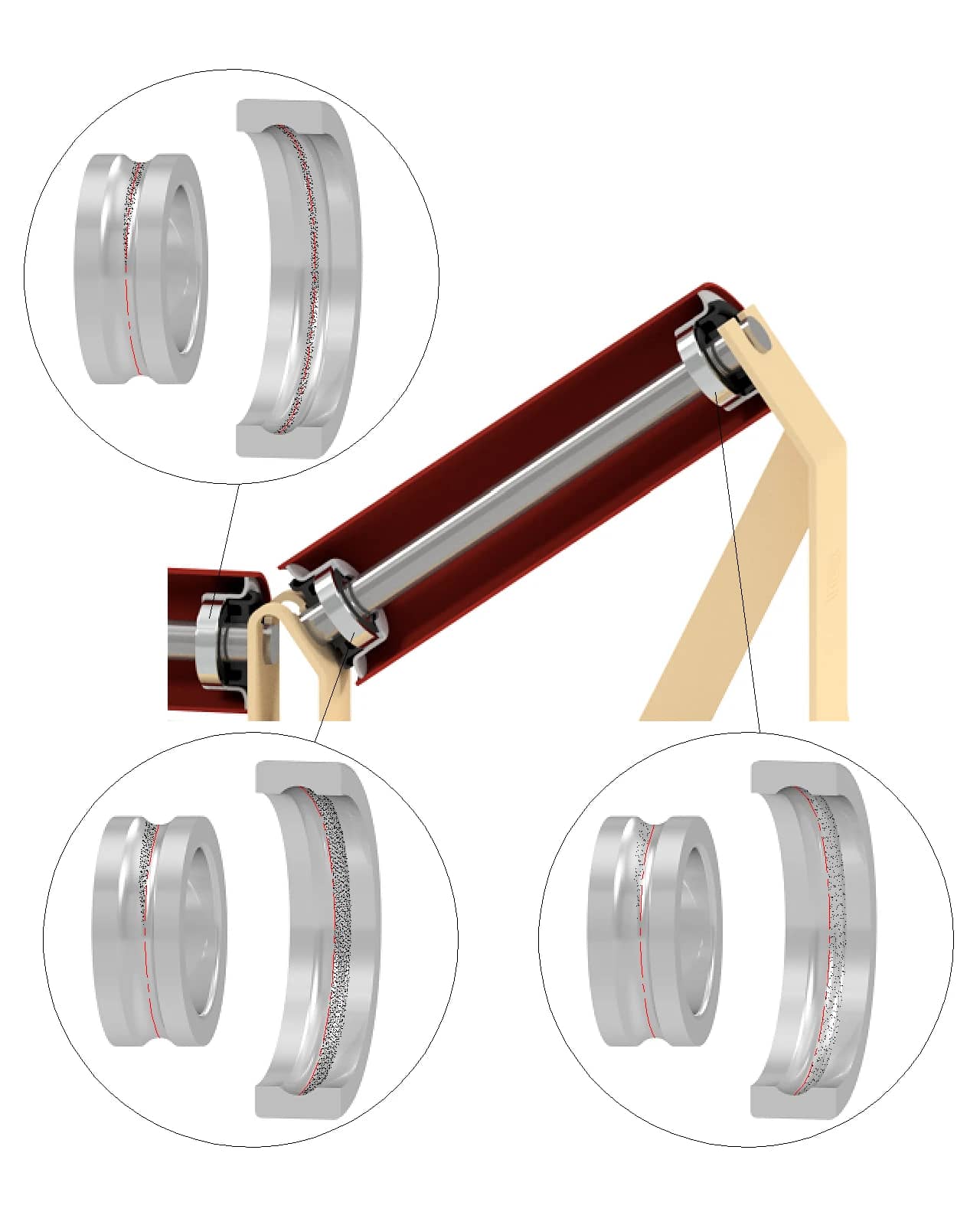
Accurately mounted bearings
Centre roller: a trace consistent with a vertical radial load.
Wing roller, lower bearing: a trace reflecting the highest portion of the roller's combined axial and radial load.
Wing roller, upper bearing: a trace reflecting the lowest portion of the roller's combined axial and radial load.
Flat return roller traces are similar to those of a centre carry roller. V-return roller traces are a combination of the centre and wing carry roller traces.
Accurately mounted bearings. Top: centre roller with a vertical radial load. Bottom: the lower and upper bearings of a wing roller, carrying the highest and lowest portions of the roller's combined axial and radial load
Tracks on composite rollers tend to be wider than on steel because of the greater coefficient of thermal expansion and the greater flexibility of the composite shell.
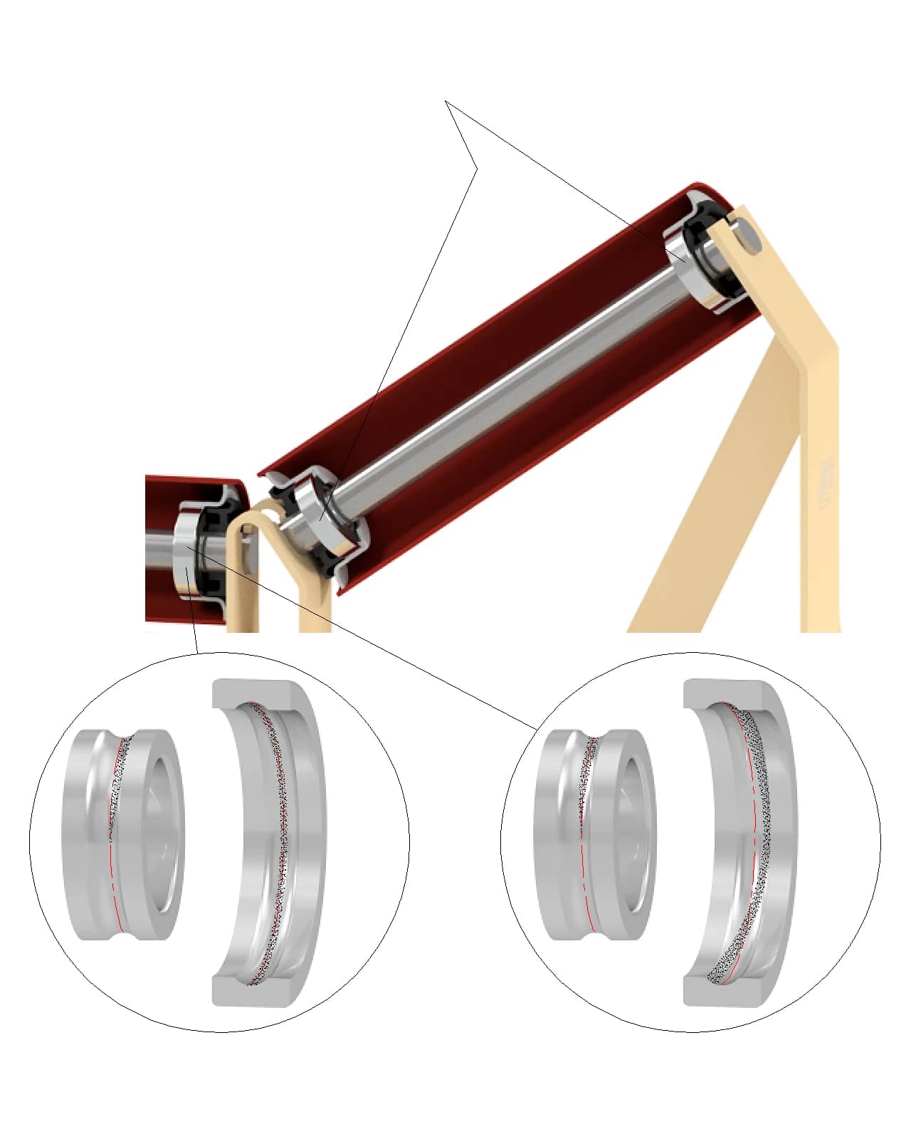
Misaligned bearings
A misaligned shaft shows on the inner raceway and a misaligned bearing housing shows on the outer raceway. The example below shows the typical contact trace for excessive shaft misalignment under load, for a centre roller.
The traces for the bearings in a wing roller are a modified combination of the traces for accurately mounted bearings and those for misaligned bearings.
Misaligned bearings, centre roller. Left: misaligned shaft, seen on the inner raceway. Right: misaligned bearing housing, seen on the outer raceway
Photographic examples of bearing failure
The photographs below show common failure initiators and failure types found in conveyor rollers. For more detailed, high-definition photographs, refer to ISO 15243 or to the publications of the bearing suppliers.
Plastic deformation
Visible at the outer edge of the raceway, caused by axial overload.
Plastic deformation at the outer edge of the raceway from axial overload
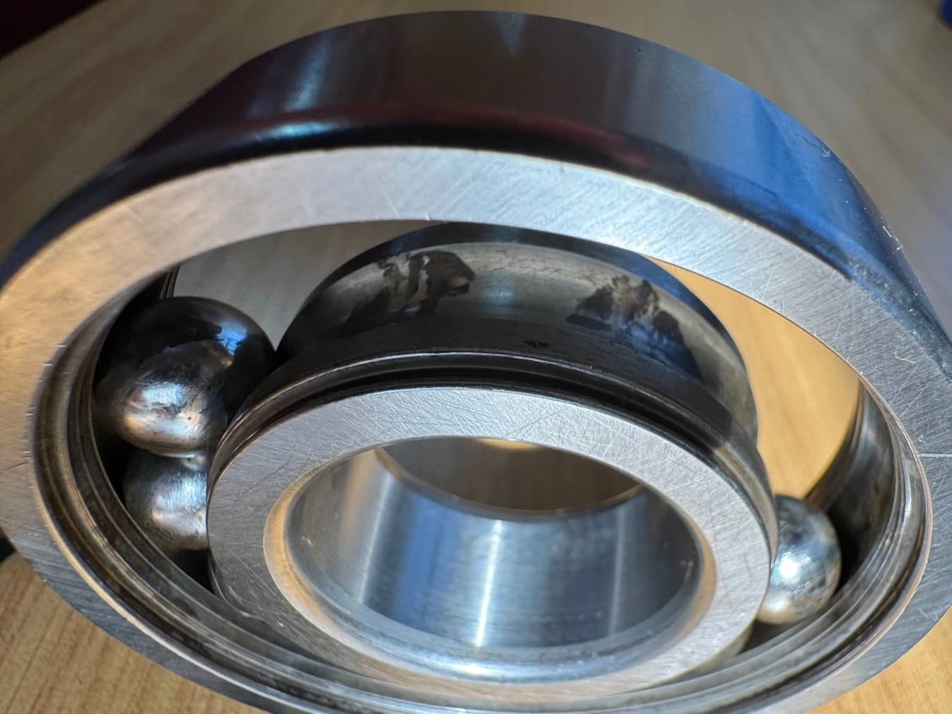
Moisture corrosion
Visible at the contact points on both the raceway and the balls.
Moisture corrosion at the contact points on the raceway and balls
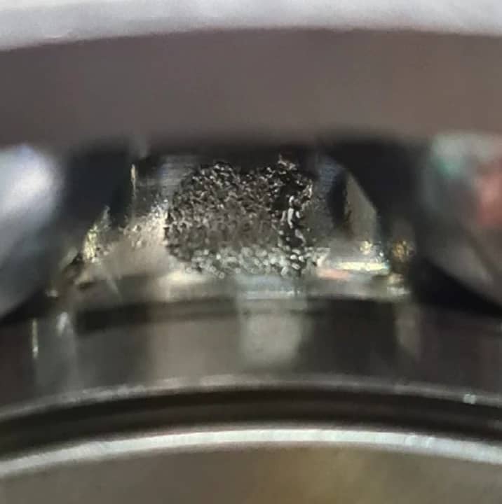
Spalling
Where spalling occurs at the ball pitch, the damage was most likely initiated while the roller was stationary.
Spalling on the raceway
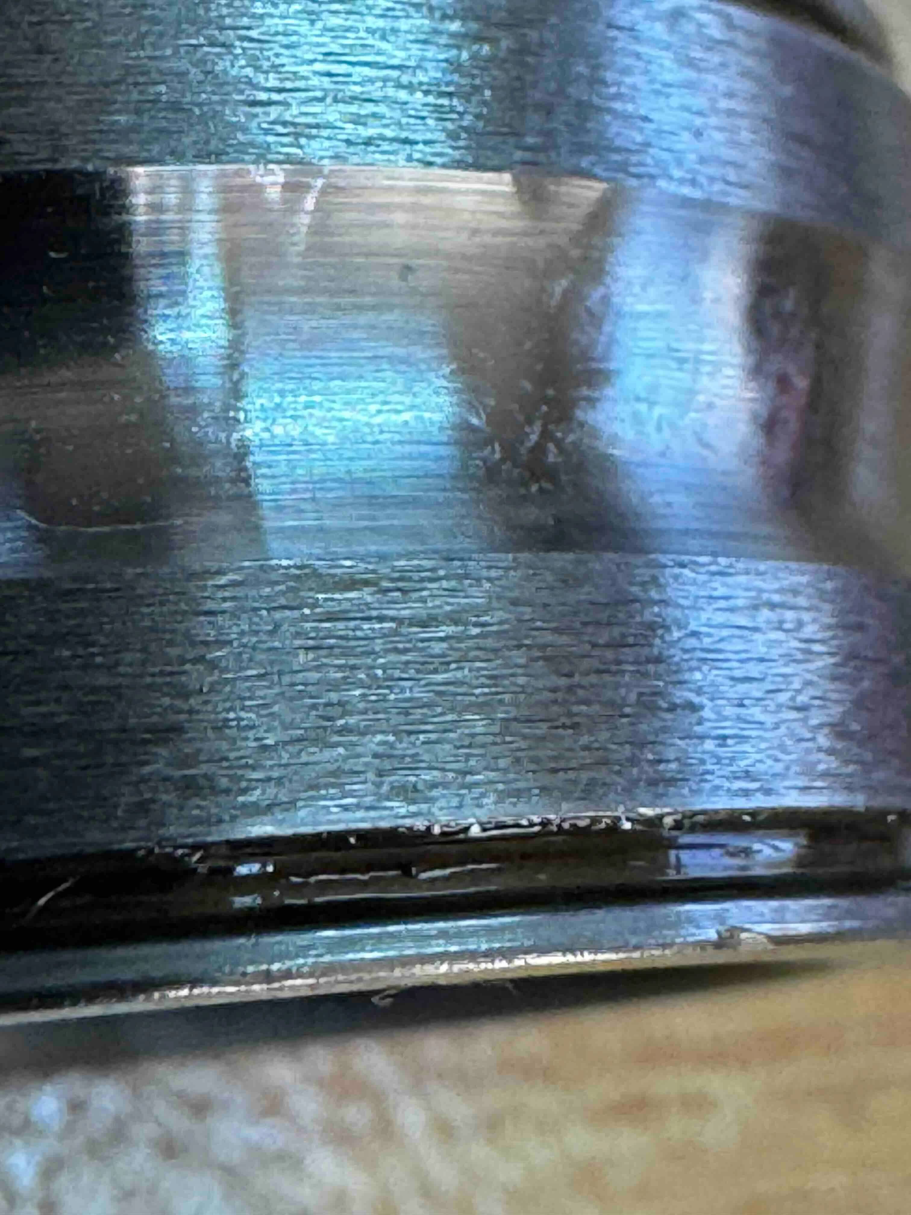
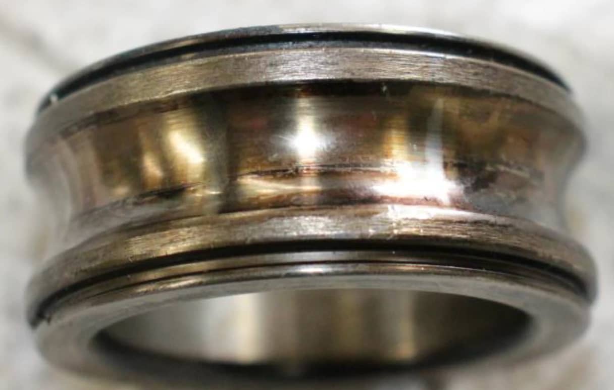
Overheating
Overheating can result from several failure mechanisms. In this case it is seen as discolouration of the inner ring.
Overheating: discolouration of the inner ring
Lack of lubrication
Discolouration of the raceway itself can be a sign that the initial grease fill was absent.
Lack of lubrication: discoloured raceway where the initial grease fill was absent
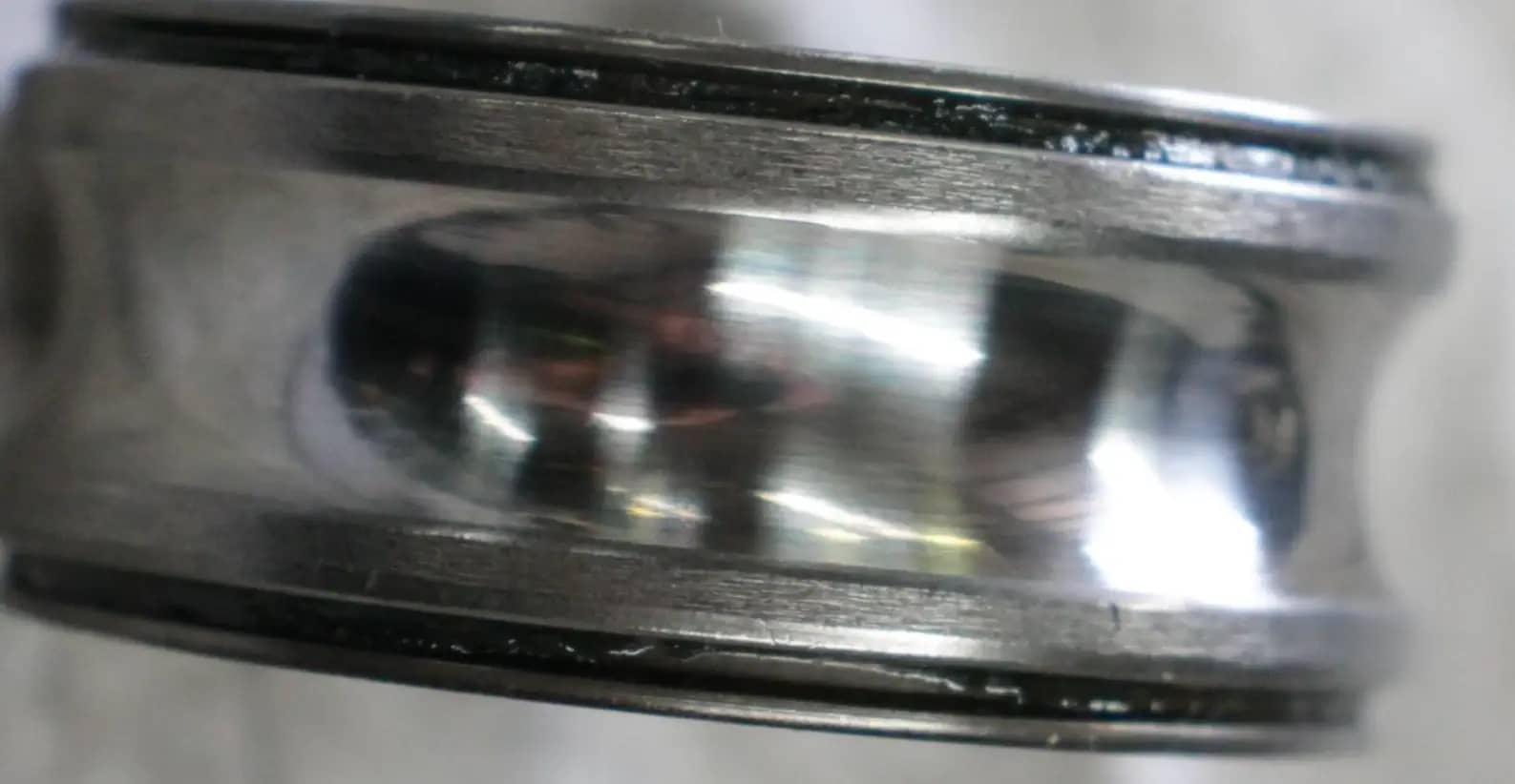
Shaft movement
A wide wear pattern on the inner race of a centre roller indicates shaft movement, in this case caused by bearing or seat failure at the opposite end of the roller.
Shaft movement: wide wear pattern on the inner race of a centre roller
Best practices for bearing inspection
To analyse a failure properly, the bearing must be dismantled correctly. Bearings should be removed from the roller carefully, so that no further damage is introduced that could mask or complicate the analysis of the failure mode.
Recommended dismantling procedure:
Clean and photograph. Clean the outside of the bearing to avoid contaminating the dismantled parts, then photograph its outside surfaces.
Remove the seals. Prise off the bearing seals, if fitted.
Inspect the grease. Photograph both sides to document the appearance of the grease, and take samples for analysis if required.
Cut the bearing. Choose a cut line between the balls and cut the bearing in half, using a non-aggressive method such as a precision diamond wire saw.
Final analysis. Clean all running surfaces, balls and cages, then photograph and analyse every component.
Recorded consistently, the photographs, grease observations and contact traces from each dismantled bearing build the history that makes the root cause of the next failure easier to identify.
Frequently asked questions
Do idler roller bearings give warning before they fail?
Usually. Noise and vibration typically appear weeks before a catastrophic failure, and rollers fitted with monitoring sensors report it sooner, with temperature and rotational speed as well. Stop the belt and remove suspect rollers early: extensive damage destroys the evidence needed for root-cause analysis.
What do contact traces on a bearing raceway show?
How load is applied to the bearing and how accurately it is fitted. Visible tracks after running-in are normal. For maximum life they should be consistent and stay clear of the raceway edges; a misaligned shaft marks the inner raceway, a misaligned housing the outer.
How should a failed idler bearing be dismantled for analysis?
Clean and photograph the outside, prise off the seals, then photograph and sample the grease. Cut the bearing in half between the balls with a non-aggressive method such as a precision diamond wire saw, then clean, photograph and analyse every running surface, ball and cage.