Allowable limits, monitoring methods, and the consequences of wear
Lorbrand Engineering10 October 202614 min read
Introduction
The global conveyor industry has seen a decisive shift from traditional steel idler rollers towards composite alternatives over the past decade. Modern composite conveyor rollers, glass-fibre reinforced high-density polyethylene (GF-HDPE) tubes with engineering-class nylon or GF-HDPE bearing housings, now represent a rapidly growing share of new roller installations across mining, quarrying, port, and bulk-materials-handling operations. Their advantages are compelling: they are 20–60% lighter than steel equivalents (depending largely on the steel shell's wall thickness), corrosion-resistant, significantly quieter (up to 10 dB), and "belt-friendly" in the event of a seizure, with no sharp steel edge to destroy the belt.
≈20 mm
composite shell wall, roughly 3–5× the 4–6 mm of a steel shell, providing the wear reservoir
A defining characteristic of composite rollers is their substantially thicker shell wall. Where a steel shell is typically 4–6 mm, a composite GF-HDPE tube is commonly 15–20 mm (and up to around 22 mm). This additional material serves both a structural and a wear-life purpose: the thicker wall is required by the lower elastic modulus and hardness of polyethylene relative to steel, and it provides a substantial wear allowance that, in theory, extends operational life.
This very characteristic raises questions the industry has not yet fully addressed. How much of that wall may safely be consumed before a roller must be replaced? How can wear be measured or monitored practically on conveyors where thousands of rollers are installed? And, increasingly important under tightening environmental regulation, what happens to the polyethylene that is worn away? This article, drawn from Lorbrand's four decades in conveyor-component design and more than a decade of specific composite-roller experience, explores each in turn.
Two construction methods dominate the market for heavy-duty composite rollers. Pressed-in bearing housings use glass-fibre-filled engineering nylon (typically PA6-GF or PA66-GF), injection moulded with calibrated bearing seats and press-fitted into the ends of the GF-HDPE tube; GF-PA66 has a Vicat softening temperature typically above 250 °C and a heat-deflection temperature that can exceed 230 °C under load. Friction-welded bearing housings use GF-HDPE housings rotationally friction-welded to the GF-HDPE tube, fusing housing and tube into a single continuous structure.
In both designs the GF-HDPE tube is the wear surface. New-roller outside diameters conform to CEMA or equivalent standards (commonly 127, 152, or 178 mm). The glass-fibre reinforcement substantially improves the tube's stiffness, creep resistance, and load-bearing capacity over unreinforced HDPE. Lorbrand manufactures GF-HDPE tube in a range of standard diameters, in wall thicknesses that vary with each application's load and deflection requirements.
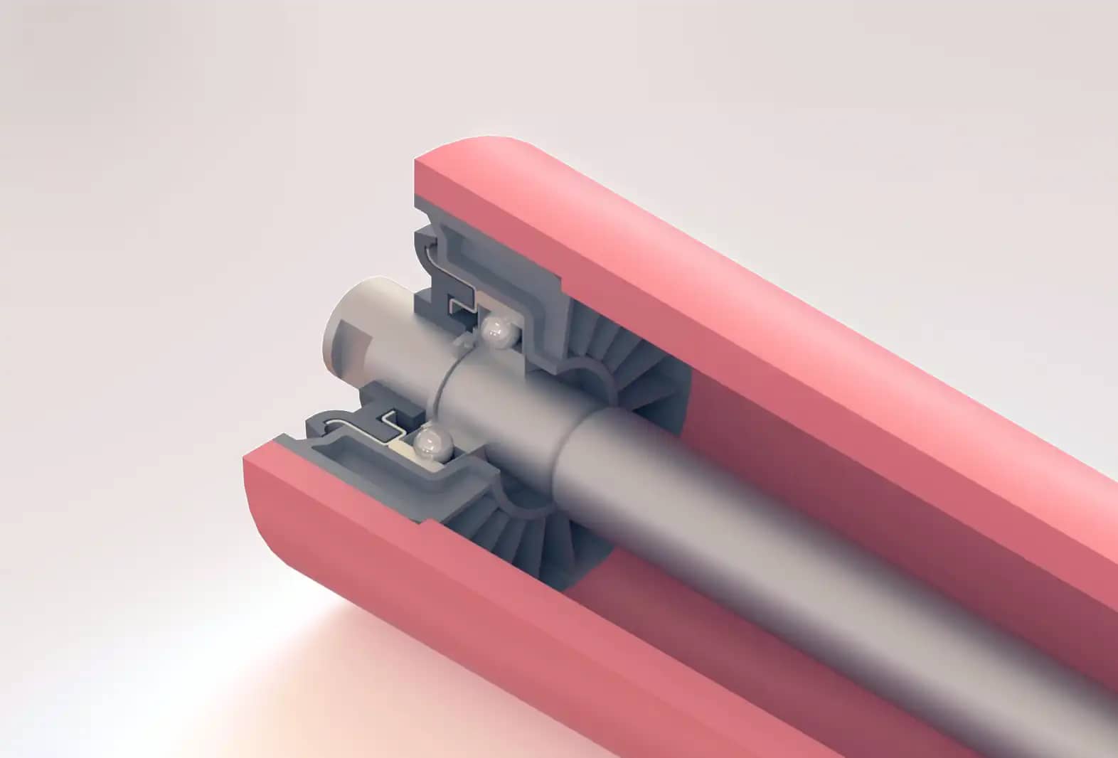
Quarter-section render of a composite roller, showing its internal construction
Wear mechanisms
Shell wear occurs through several mechanisms. Abrasive wear from the belt underside is the primary mechanism on carry-side rollers: the belt acts as a continuously moving abrasive surface against the rotating shell, particularly when conveying iron ore, coal, or aggregates. On return-side rollers, carryback adhering to the belt's dirty side generates localised, often more aggressive wear. Wind-blown dust, rain-driven slurry, and UV embrittlement of the surface layer all contribute, and impact at transfer and feed zones causes localised deformation and accelerated wear.
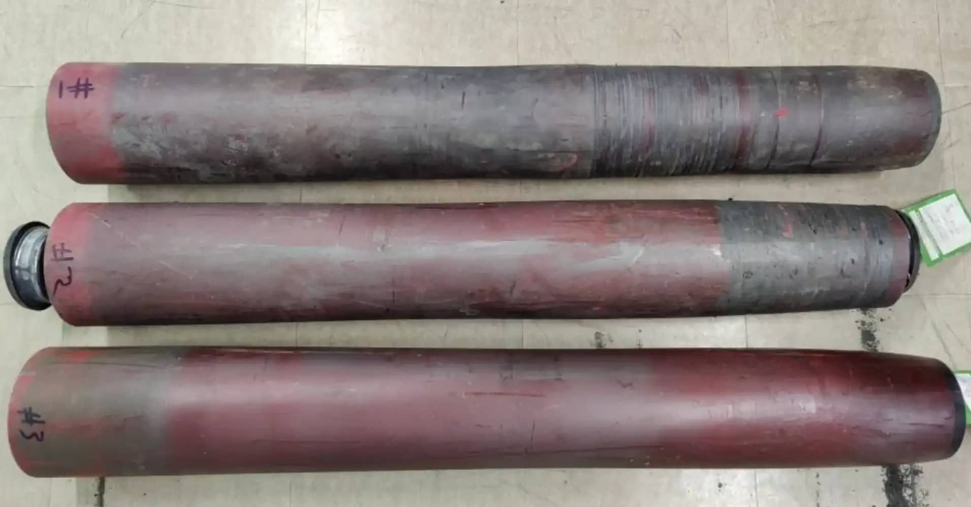
The wear pattern is rarely uniform. Centre rollers in a troughed set wear faster than wing rollers under higher material-load contact pressure, and wear concentrates towards the centre of the face. Temporary seizures create flat spots, which become stress concentrations that accelerate subsequent fatigue-related wear.
The accelerating wear rate
Why it mattersWear is not linear: years to lose the first 3 mm, then weeks from 5 mm to failure.
A critically important characteristic, and one that distinguishes composite wear from the minor wear seen on steel, is that the wear rate does not stay constant as the roller wears down. It accelerates, and the relationship is approximately exponential rather than linear.
The mechanism is differential surface speed at the belt-roller interface. The belt travels at one fixed linear speed. A new roller has a uniform diameter and rolls without sliding. As it wears non-uniformly, fastest at the loaded centre, it develops a concave, "hourglass" profile. Surface speed is proportional to local diameter (\( \pi D n \)𝜋𝐷𝑛), so the worn centre now moves slower than the belt, and the mismatch is accommodated by sliding. That sliding is abrasive, and it concentrates in exactly the zones that are already most worn: wear causes sliding, sliding causes more wear, and the process feeds back on itself. (The roller is rigid and turns at a single RPM set by torque equilibrium across the contact zone, which corresponds to a pressure-weighted effective diameter biased towards, but not equal to, the worn centre. Forward slip at the worn centre coexists with backward slip at the unworn edges, with near-pure rolling in between.)
The practical consequence is a steepening wear curve: a roller may take years to wear from 0 to 3 mm, only months from 3 to 5 mm, and weeks from 5 mm towards structural failure. Where a large roller population was installed at once, as is common on new or refurbished conveyors, those rollers can enter the accelerating phase together, producing a "batch failure" cascade that overwhelms maintenance capacity and causes sustained downtime. This is why proactive monitoring matters: waiting for visible failure risks missing the inflection point, whereas continuous RPM-based wear detection can catch the acceleration while there is still time for an orderly replacement programme.
Belt-tracking implications of shell wear
A belt always migrates towards the larger-diameter side of a roller, the principle behind crowned and self-aligning idlers. The same principle means non-uniform shell wear can induce mistracking that emerges gradually on a conveyor that tracked well when new. Asymmetric wear across a centre roller's face acts as an unintended taper; if that asymmetry repeats across a run of idlers, the cumulative steering can drive significant belt displacement, edge damage, and spillage.
On steel rollers, allowable wear is minimal, so these effects rarely have time to develop. On composite rollers, where far more radial wear is tolerated, the diameter changes, and the tracking effects, are larger and have more time to accumulate. The problem is compounded by the lower coefficient of friction at the HDPE-on-rubber interface (\( \mu \approx 0.2 - 0.3 \)𝜇≈0.2−0.3 versus steel-on-rubber \( \mu \approx 0.35 - 0.5 \)𝜇≈0.35−0.5), which reduces the belt's self-centring force by 30–40%. This is why composite-rollered conveyors routinely require more edge guide rollers than equivalent steel installations. Where the belt runs persistently against those guides, running resistance rises and belt-edge wear accelerates, degrading the very belt the composite roller was meant to protect.
Roller replacement and uneven loading
Good practiceReplace worn rollers as a set: a lone new roller among worn neighbours is overloaded from day one.
When a single worn roller is replaced with a new one, the new roller stands proud of its worn neighbours by the depth of their accumulated wear. On a carry-side centre roller, even a few millimetres of height difference can sharply increase the load the replacement carries. Under tension, the belt changes angle more abruptly at the higher roller, concentrating both the normal material load and the belt-tension deviation forces onto that single unit. At typical carry-side idler spacings of 1.2–1.5 m and moderate-to-high belt tensions, the load on the replacement roller can exceed its design ratings for shell strength, bearing-housing capacity, and bearing L10 life.
The overloaded new roller also wears faster from the outset: the higher contact pressure raises the abrasive wear rate, feeding straight into the self-reinforcing loop between wear and sliding described earlier in this section. Its shell deflection can likewise exceed design expectations, eroding the structural safety margin from day one. The surrounding worn rollers, meanwhile, are partially unloaded as the belt bridges over them to the higher new roller. This looks beneficial, but it means their wear indicators no longer represent the load they will carry once their neighbours are replaced in turn.
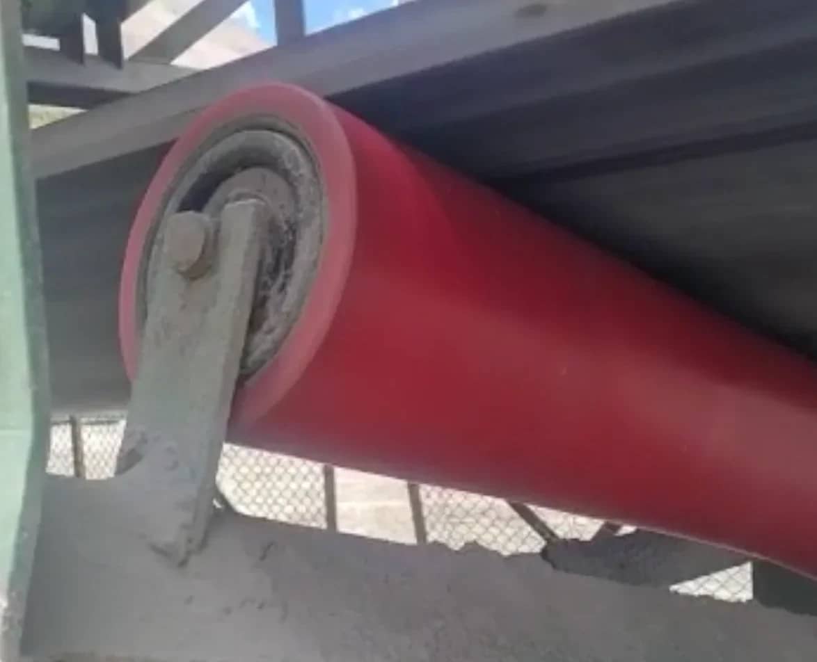
An extreme example: a composite V return roller with uneven face wear from running in carryback piles
Good practice is therefore to replace all rollers on a conveyor section that are approaching the wear limit together, rather than swapping individual rollers as each one reaches the threshold. This carries direct maintenance-planning implications: enough spare rollers must be held in stock to allow batch replacement, and shutdown windows must accommodate the larger volume of work. The cost of replacing rollers that have not quite reached their absolute limit is more than offset by avoiding the overload damage, accelerated wear, and bearing failures that follow from mixing new and heavily worn rollers on the same conveyor.
The exception is return rollers and other low-tension positions, where the load per roller is modest and the increase on a single replacement is proportionally smaller; there, individual change-out may be acceptable. Confirm this on a case-by-case basis with the roller supplier.
Allowable shell wear limits
The challenge of a universal limit
Unlike steel shells, which either maintain structural integrity or fail suddenly by cracking or perforation, composite shells degrade gradually, and a single universal maximum allowable wear depth is not straightforward to define.
The widely cited 5 mm radial-wear planning threshold deserves context. It is closely associated with manufacturers who build visual wear indicators into their tubes using a dual-layer construction with a colour-change boundary at a fixed depth. For manufacturing practicality they standardise on one indicator depth, commonly 5 mm, across the range rather than varying it per diameter, wall, or application. The figure therefore reflects a product-standardisation decision as much as a universal engineering limit.
7–9 mm
radial wear on a 20 mm wall beyond which failure rates rise markedly; treat as an absolute ceiling
How much wear a specific roller can tolerate depends on the manufacturer's factor of safety and the site-specific factors below. A conservatively designed roller may tolerate more than 5 mm; one operating near its rated capacity may be unfit well before it. What is consistent across the industry is that once radial wear passes roughly 7–9 mm on a typical 20 mm wall, the remaining section can no longer sustain cyclic loading without stress concentrations, and fatigue life is significantly compromised.
Wear-limit summary
The following is a general guide for a typical 152 mm roller with a 20 mm wall. Consult your supplier for application-specific guidance.
Radial wear (mm)
OD (mm)
Wall remaining (mm)
Wall consumed
Status / action
0
152
20
0%
New roller, baseline
2–3
146–148
17–18
10–15%
Normal service wear
5
142
15
25%
Typical supplier planning threshold
7–9
134–138
11–13
35–45%
Elevated failure risk, replace urgently
>10
<132
<10
>50%
Structural compromise, imminent failure
Factors affecting the allowable limit
The thresholds above are general guidelines. Several factors shift the point at which a specific roller becomes unfit for service:
Manufacturer's factor of safety. Different suppliers size shell walls differently for a given CEMA class, diameter, and belt width; more margin means more tolerable wear. Seek guidance for the roller as supplied.
Loading. A roller at 40% of rated capacity has far more margin at a given wear depth than one at 90%. Highly loaded rollers should be replaced at lower wear values.
Roller length and deflection margin. Suppliers often keep the same diameter for longer return or "V" rollers as for shorter carry rollers. Because deflection rises with span, those longer rollers already sit closer to their deflection limit when new, and as the wall thins, stiffness drops and deflection grows. A longer roller will reach shell failure at a lower wear depth than a shorter one of the same diameter, even installed at the same time.
Wear uniformity. Localised wear is far more dangerous than uniform wear: a 10 mm groove on an otherwise 5 mm-worn roller can be riskier than 7 mm of uniform wear, because grooves and flat spots are stress risers under cyclic load.
Temperature and UV exposure. HDPE softens slightly when hot and embrittles under sustained UV. A roller that has suffered UV degradation may fail at a lower wear depth than one in a covered or underground installation.
Accelerating wear rate. As above, the window between planning threshold and structural failure can be much shorter than a linear extrapolation of early wear suggests, and a simultaneously installed population can enter that window together.
Belt-tracking degradation. A roller can be structurally adequate yet operationally unacceptable because its wear profile is causing mistracking, edge damage, or spillage. Treat tracking degradation as an additional replacement criterion.
Practical wear measurement and monitoring
Measuring shell wear on composite rollers is genuinely difficult. Unlike steel rollers, where failure is essentially binary, composite rollers degrade gradually, and the value of monitoring lies in catching wear early enough to plan replacements into scheduled shutdowns rather than reacting to failures.
Visual wear indicators
Some manufacturers offer an integrated visual indicator: a dual-layer tube where a contrasting inner colour becomes visible once wear reaches the indicator depth (commonly ~5 mm). The concept is simple and needs no instrumentation, but its practical limitations are significant. Inspecting every roller is labour-intensive, and rollers are frequently not visible, and covers or guards may need removal. In Lorbrand's field experience, the indicator is usually obscured: carry-side surfaces are hidden by the belt during operation and by spillage, dust, and compacted fines when stopped; return-side surfaces are masked by the belt and carryback; wet environments bond a slurry layer to the HDPE. A technician walking the belt is far more likely to see a uniformly dirty roller than a clean colour-coded one. Visual indicators are a useful supplementary check when conditions happen to be favourable, but a programme built solely around them will almost certainly miss worn rollers.
Manual measurement
Direct diameter measurement with external calipers, a pi-tape, or a laser gauge during a belt stoppage is accurate (the measured diameter against nominal gives diametral wear, halved for radial depth), but requires the surface to be accessible and clean. Measuring every roller at a multi-thousand-roller site is impractical outside extended shutdowns, so a pragmatic approach samples representative rollers in known high-wear zones (loading zones, curves, heavily loaded carry-side centres). Ultrasonic wall measurement, routine on steel, is less reliable on HDPE because of the material's viscoelasticity, acoustic attenuation, and signal scattering from the glass fibre.
Embedded monitoring technology
±0.05%
RPM-measurement tolerance that lets embedded monitoring infer shell wear continuously, without belt stoppages or visual access
The most promising development is embedded monitoring: sensor modules fitted during manufacture that gather operational data and transmit it wirelessly. Lorbrand's Sensor Seal is one such device, installed at the roller end to capture temperature, vibration, and RPM. RPM is directly relevant to wear: as the shell wears and diameter falls, the roller must spin faster for the same belt speed. Comparing measured RPM against the expected value for the original diameter and known belt speed yields the effective diameter reduction, and hence radial wear, at high accuracy. Temperature trending at 0.1 °C resolution gives early warning of bearing degradation, and the onboard accelerometer enables vibration-based defect detection, with machine-learning analysis predicting failures and estimating remaining life.
One subtlety: measured RPM reflects the pressure-weighted effective diameter rather than the peak wear depth at the most-worn point. The relationship between the two depends on the wear-profile shape and pressure distribution, which are application-specific and change as wear progresses, so Vbelt=π D · n (with n the roller's RPM) slightly underestimates peak wear. For accurate peak-wear quantification, a one-time calibration, physically measuring a sample of rollers at varying wear stages against concurrent RPM readings, establishes the site-specific conversion factor, after which continuous RPM trending can drive threshold-based replacement alerts with confidence.
The decisive advantage over indicators and manual measurement is continuous, automated, quantitative trending for every instrumented roller, with no inspection, stoppage, or visual access required. It works equally on carry- and return-side rollers, in dust or wet, covered or open, on conveyors that are difficult or unsafe to reach.
For most operations a layered approach gives the best balance of cost and effectiveness: routine walk-the-belt inspections for unusual wear, seizures, cracking, or delamination; targeted manual diameter measurement during planned shutdowns, focused on high-wear zones and rollers flagged visually; and, where scale and criticality justify it, embedded monitoring prioritised on critical conveyors, high-wear zones, and inaccessible runs such as overlands or underground installations. The data from embedded monitoring is the foundation for genuinely predictive replacement, in place of time-based or reactive programmes.
Environmental considerations: the microplastics question
Quantifying the material loss
This is the aspect of composite-roller wear the industry has been slowest to confront, yet arguably the most consequential for regulation and reputation. When a shell wears, the material does not disappear. It leaves as fine particles deposited in the operating environment. The question is how much, and in what form.
Consider a CEMA D6 three-roll troughing set on a 1200 mm belt: three rollers, each ~450 mm face length, 152 mm OD, 20 mm wall. Because wear is deepest at the centre, take average radial wear as roughly half the peak, 2.5 mm average at the 5 mm replacement threshold. The volume removed per roller is then:
EQ 1 · SHELL WEAR VOLUME
V = \pi L (R_{\text{out}}^{2} - R_{\text{worn}}^{2})
𝑉=𝜋𝐿(𝑅2out−𝑅2worn)
At GF-HDPE density ρ ≈ 1.1 g/cm³ → ≈ 0.6 kg per roller, or ≈ 1.8 kg per three-roll set.
≈10 t
GF-HDPE shed by the rollers of a 5 km overland conveyor over their wear life, roughly doubling if 10 mm wear is accepted
Scale that up: a 5 km overland conveyor with carry-side idlers at 1.2 m spacing has ~4,167 idlers. If each reaches 5 mm peak wear over its life, the carry side alone sheds ~7.5 tonnes of HDPE onto the ground. Adding return-side rollers (spaced at roughly three times the carry spacing, ~2.5 tonnes) gives a combined total of approximately 10 tonnes over the wear life of the roller population. Accept 10 mm of wear before replacement and that figure roughly doubles. These are not trivial quantities, and the debris includes released glass fibres. Steel-roller wear produces inert, naturally occurring iron-oxide dust.
Regulatory and compliance considerations
Microplastic regulation is evolving rapidly. The EU has already restricted intentionally added microplastics in certain products and is developing frameworks for unintentional release. Mining operations face environmental impact assessments and compliance obligations that increasingly require characterisation of all waste streams, including diffuse sources. Operators should recognise that polymer wear components collectively (composite rollers, UHMWPE liners, polymer skirting, polyurethane belt cleaners) generate a cumulative microplastic load that may attract scrutiny as detection methods and frameworks mature. Proactive assessment positions operators ahead of regulation.
Recommendations for conveyor operators
Adopt the supplier's recommended radial-wear limit (e.g. 5 mm) as a planning threshold. Confirm the figure with your manufacturer, since it varies with the shell's factor of safety, diameter, wall, and the application's load and deflection. Do not routinely run rollers beyond 7 mm of radial wear on a 20 mm wall without specific engineering justification.
Replace rollers as a set. A single new roller among worn neighbours stands proud and can be loaded beyond its shell, housing, and bearing ratings, wearing fast from day one and risking premature bearing failure. Replace all rollers approaching the limit on a section together, and hold enough spares to do so. Individual change-out is usually acceptable only at low-tension return positions; confirm with your supplier.
Implement a systematic wear-monitoring programme. Combine visual inspection with targeted manual measurement during shutdowns and, where scale and criticality justify it, embedded monitoring such as Sensor Seal. Trend wear by conveyor zone to find high-wear locations and optimise replacement intervals.
Characterise and quantify the microplastic load. Estimate the total HDPE mass that will be consumed over the conveyor's design life, alongside other polymer wear sources, and include it in environmental impact assessments and monitoring.
Consider mitigation for microplastic deposition. In environmentally sensitive areas, near waterways, or under emerging regulation, consider containment trays or sheeting beneath conveyors, periodic collection and proper disposal, and covered or sealed structures that limit wind dispersal.
Collect and responsibly manage worn-out rollers. Glass-fibre content complicates recycling: fibres accelerate wear on processing equipment, are hard to separate, and degrade recycled output, while field contaminants add difficulty. GF-HDPE generally cannot enter standard HDPE recycling streams; establish dedicated collection and discuss end-of-life options with your supplier. Treat landfill as a last resort.
Conclusion
Composite HDPE idler rollers are a genuine advance in conveyor technology, and their advantages in weight, noise, corrosion resistance, and belt-friendliness continue to drive adoption. But the thicker shell wall, the source of their wear-life advantage, demands wear-monitoring and management approaches different from those developed over decades for steel.
There is no single universal wear limit. The allowable radial wear depends on the manufacturer's factor of safety, the operating load relative to rated capacity, span and deflection, wear uniformity, tracking considerations, and environmental exposure. Work with your supplier to set application-specific thresholds, and don't assume a limit published for one product applies to another. What is consistent is that wear beyond 7–9 mm on a 20 mm wall sharply elevates failure risk. Treat that range as an absolute ceiling.
Visual wear indicators, though a useful concept, are often obscured in real conditions and cannot be the sole monitoring method. Embedded monitoring such as Sensor Seal provides the continuous, quantitative, condition-independent data that makes genuinely predictive maintenance possible. And the industry must confront the environmental dimension: the microplastic quantities shed over the life of a major conveyor are significant, measurable and, under tightening regulation, increasingly likely to attract scrutiny.
Frequently asked questions
At what wear depth should a composite roller be replaced?
Plan replacement at around 5 mm of radial wear, the common supplier planning threshold. Past roughly 7–9 mm on a typical 20 mm wall, fatigue life drops sharply and replacement is urgent. The actual limit depends on the roller's design margin, its load and length, and how evenly it has worn.
Why does composite roller wear speed up over time?
The loaded centre of the shell wears fastest, giving an hourglass profile. The worn centre then turns slower than the belt, and the difference is taken up by abrasive sliding, which wears it faster still. A roller can take years to reach 3 mm of wear and only weeks to go from 5 mm towards failure.
Should worn composite rollers be replaced one at a time?
On carry-side positions, replace all rollers in a section that are nearing the wear limit together. A single new roller stands proud of its worn neighbours, carries a disproportionate share of the load and wears faster from the start. On return rollers individual change-out may be acceptable; confirm it with the roller supplier.
How can composite shell wear be monitored?
Measure diameters with calipers, a pi-tape or a laser gauge on sample rollers in high-wear zones, or use embedded sensors. Lorbrand's Sensor Seal reads roller RPM: as the shell wears, the roller turns faster for the same belt speed, which gives a running estimate of its effective diameter.